Lightning arrester and a power transmission line provided with such an arrester

a technology of power transmission line and arrester, which is applied in the installation of lighting conductors, emergency protective arrangements for limiting excess voltage/current, and arrangements responsive to excess voltage, etc., can solve the problems of increasing maintenance costs, and affecting the operation of arresters. , to achieve the effect of low manufacturing and maintenance costs, low flashover voltage, and high reliability

Active Publication Date: 2011-12-15
OTKRYTOE AKTSIONERNOE OBSCHESTVO NPO STREAMER
View PDF10 Cites 13 Cited by
  • Summary
  • Abstract
  • Description
  • Claims
  • Application Information

AI Technical Summary

Benefits of technology

[0010]It is therefore an object of the present invention to provide an arrester with a high reliability, low manufacturing and maintenance costs, low flashover voltages and a high current quenching effectiveness. Such features will make it possib

Problems solved by technology

A lightning overvoltage results in a breakdown of both gaps, so that an impulse current is shunted to the ground.
The arrester stops functioning properly and needs a replacement, which means an increase in maintenance costs.
However, arc quenching ability of a single gap is small, so that after the termination of the overvoltage, a power arc follow current continues to flow through the sparkover gap.
Therefore, a shut-off device must be activated for breaking a circuit, such breaking being quite undesirable for consumers receiving electric power from this electri

Method used


Image

  • Lightning arrester and a power transmission line provided with such an arrester
  • Lightning arrester and a power transmission line provided with such an arrester
  • Lightning arrester and a power transmission line provided with such an arrester

Examples


Embodiment Construction

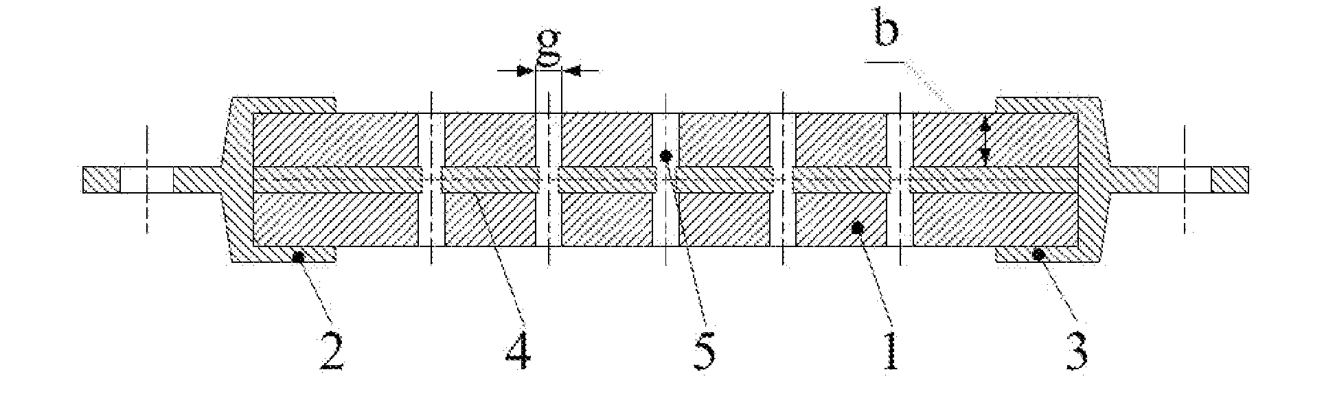
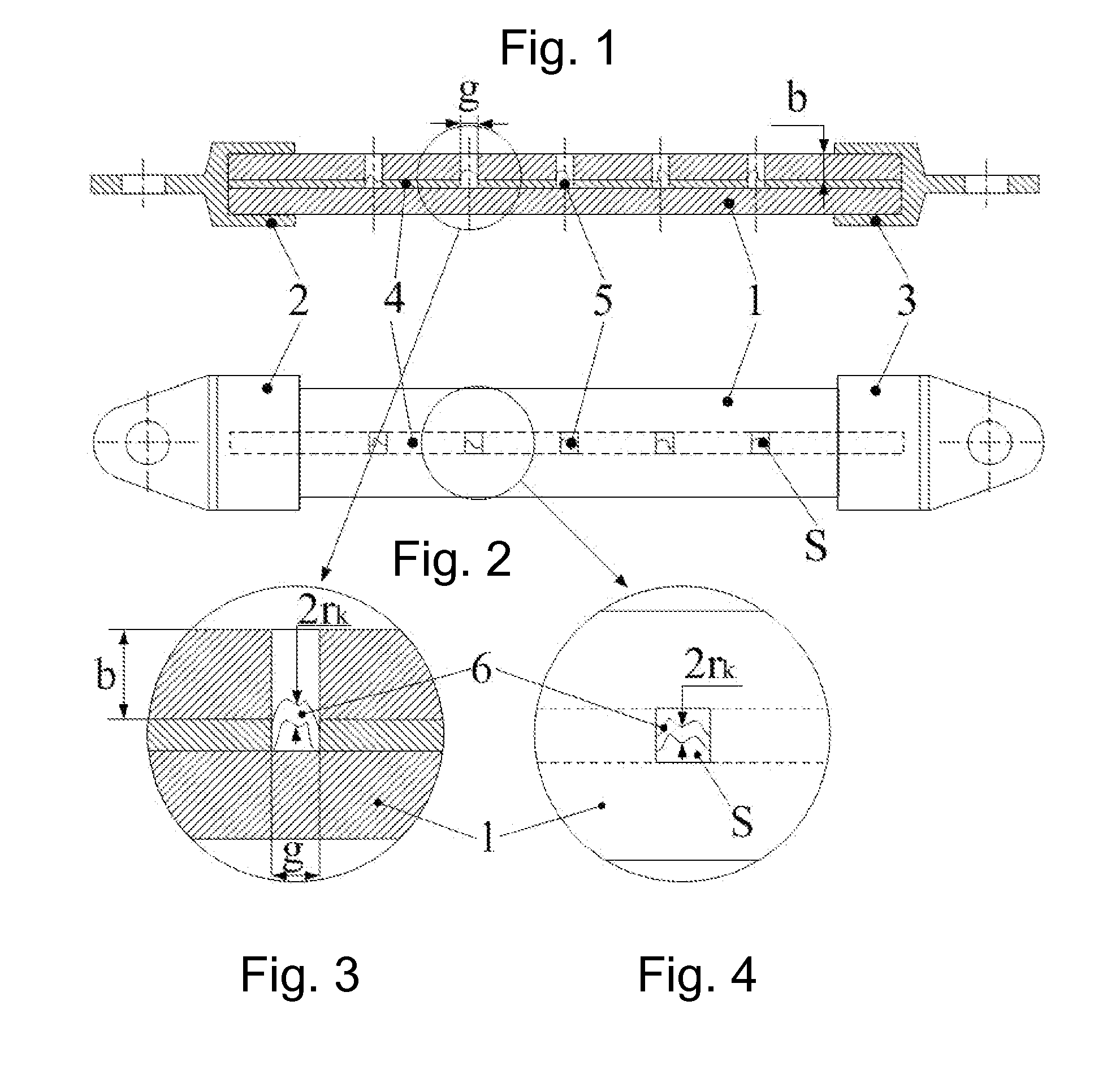
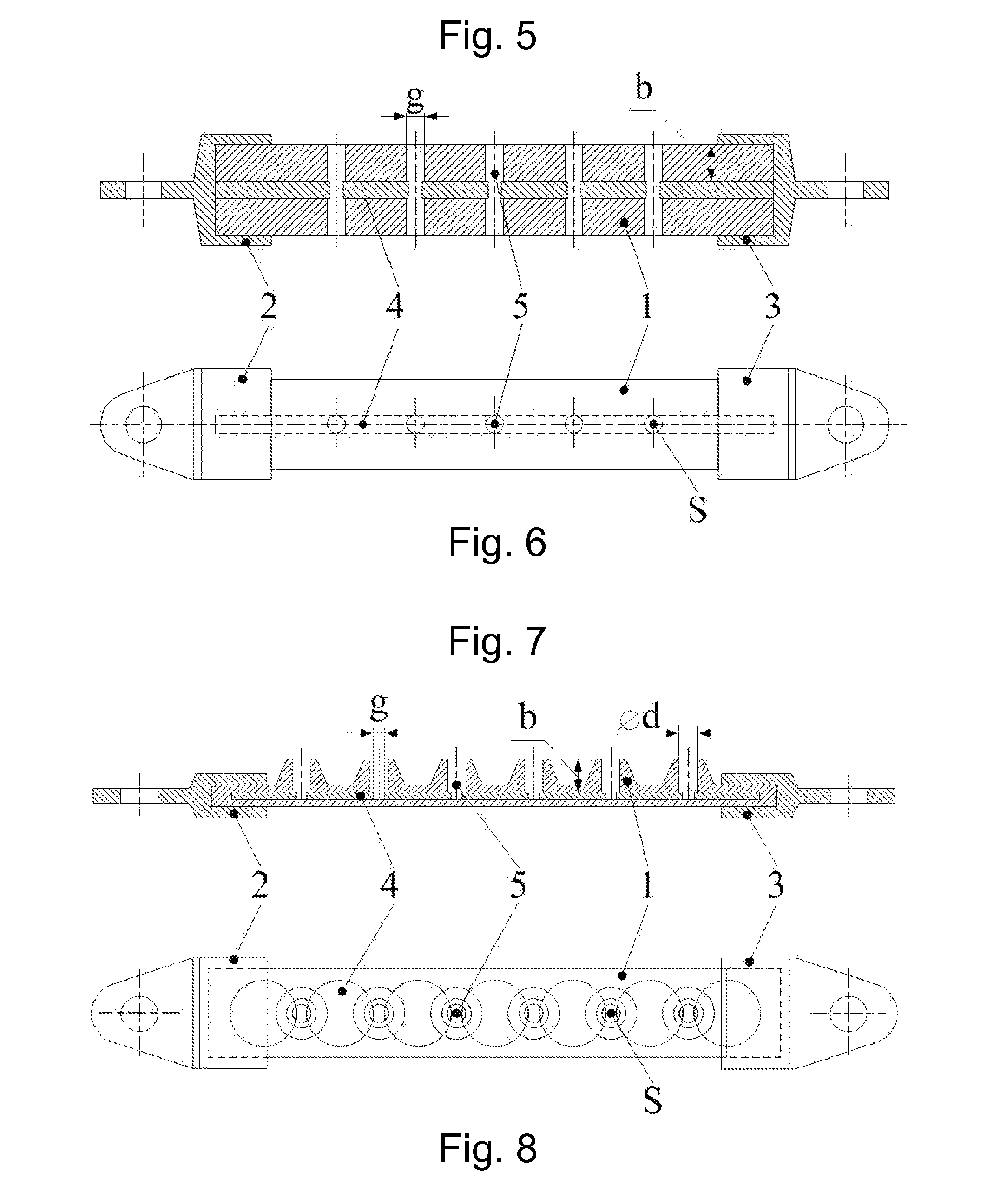
[0044]With reference to FIGS. 1 to 4, an arrester according to the invention comprises an elongated flat insulating body 1 made of a solid dielectric, for example, of polyethylene. The first and the second main electrodes 2, 3 are respectively installed on both ends of the insulating body 1. Due to such arrangement, both main electrodes are mechanically coupled to the insulating body. Inside the insulating body 1 m intermediate electrodes 4 are located. A minimal value of m equals two, while an optimal number of the intermediate electrodes is selected depending on their particular configuration, a precalculated overvoltage and other conditions of their functioning. The arrester embodiment shown in FIGS. 1 to 4 comprises 5 intermediate electrodes 4 configured as rectangular plates mutually displaced along the longitudinal axis of the arrester (this axis connects main electrodes 2, 3). A sparkover air gap is formed between each pair of adjacent intermediate electrodes 4, this gap dete...


PUM


Abstract

A lightning arrester for protecting elements of electrical facilities or a power transmission line comprises an insulating body which is made of a solid dielectric, preferably in the form of a bar, a strip or a cylinder, two main electrodes that are mechanically coupled to the insulating body and two or more intermediate electrodes. The intermediate electrodes, preferably made in the form of bars or cylinders, are arranged between the main electrodes so that said intermediate electrodes are mutually shifted along the longitudinal axis of the insulating body or along a spiral line. Such design makes it possible to form a discharge channel between the adjacent electrodes. Furthermore, said electrodes are located inside the insulating body and are separated from the surface of the body by an insulation layer. Discharge chambers formed as cavities or through bores opened to the surface of the insulating body are arranged between the pairs of the adjacent electrodes. Dimensions of the chambers are selected such that a discharge is easily blown out from the chambers to the surface of the insulating body, thereby increasing the efficiency of the discharge current quenching. In the preferred embodiments, the arrester is provided with an additional electrode for reducing a flashover voltage. Various embodiments of a power transmission line using the arrester of the invention are also disclosed.

Description

FIELD OF INVENTION[0001]The present invention relates to lightning arresters for protecting electrical equipment and high-voltage electric power lines (HEPL) against lightning overvoltages. Such arresters can be employed, for example, for protecting high-voltage installations, insulators and other HEPL elements, as well as various electrical facilities.BACKGROUND ART[0002]There is known a so-called tubular arrester for limiting overvoltages in an electric power line (cf. High voltage techniques. Ed. D. V. Razevig, Moscow, “Energiya” Publishing House, 1976, p. 287). A main element of the arrester is formed by a tube made of an insulating gas generating material. One end of the tube is plugged with a metal lid having an inner rod electrode fastened thereon. A ring-form electrode is located at an open end of the tube. A gap between the rod electrode and the ring-form electrode is called an inner, or arc quenching gap. One of the electrodes is grounded, while the second electrode is con...

Claims


Application Information

Patent Timeline
IPC IPC(8): H02H9/04
CPCH01T4/16H02H9/06H02G13/00
Inventor PODPORKIN, GEORGY VIKTOROVICHKALAKUTSKY, EUGENY SERGEEVICH
Owner OTKRYTOE AKTSIONERNOE OBSCHESTVO NPO STREAMER
Why Eureka
Try Eureka