Advanced noise reduction in digital cameras

a digital camera and noise reduction technology, applied in image enhancement, color signal processing circuits, instruments, etc., can solve the problems of increasing strength, reducing the noise of digital cameras, and containing random noise in imaging systems, so as to achieve superior image quality

Inactive Publication Date: 2011-12-29
QUALCOMM INC
View PDF20 Cites 21 Cited by
  • Summary
  • Abstract
  • Description
  • Claims
  • Application Information

AI Technical Summary

Benefits of technology

[0006]The described methods and corresponding apparatus provide ways to achieve superior image quality as compared to previous noise reduction approaches. A noise reduction apparatus is presented that includes groups of one or more serially connected non-linear filter unit groups. Each of the filter unit groups are driven by decimated input image data at a different level of decimation and the output of at least one of these groups serves as one of a plurality of inputs to another group driven at a different decimation level.

Problems solved by technology

Images obtained by digital cameras and other imaging systems contain random noise, which typically grows stronger as the ISO sensitivity grows higher.
Noise reduction in digital cameras is becoming increasingly important and problematic because of several trends in the digital camera market which result in lower Signal to Noise Ratios (SNR), including the increasing of sensor resolution by reducing the pixel size and the providing better image quality at higher ISO sensitivities, which enables capture of images in low light conditions.
The difficulty encountered with these methods is that the size of the filter required for an effective noise reduction grows in proportion to the amount of noise in the image.
However, the size of the filters is usually limited in order to save hardware costs, and software implementations tend to incur too much time and processing power to be practical.
The difficulty encountered using this method is that it affects only dark / gray areas, and it is also very likely to suppress real colors in the image.
There will always be noise when an image is captured in low light conditions.
The noise level will increase as the sensor pixel size is decreased due to sensor resolution issues and due to a trend to reduce sensor cost.

Method used


Image

  • Advanced noise reduction in digital cameras
  • Advanced noise reduction in digital cameras
  • Advanced noise reduction in digital cameras

Examples


Embodiment Construction

PTION OF THE DRAWINGS

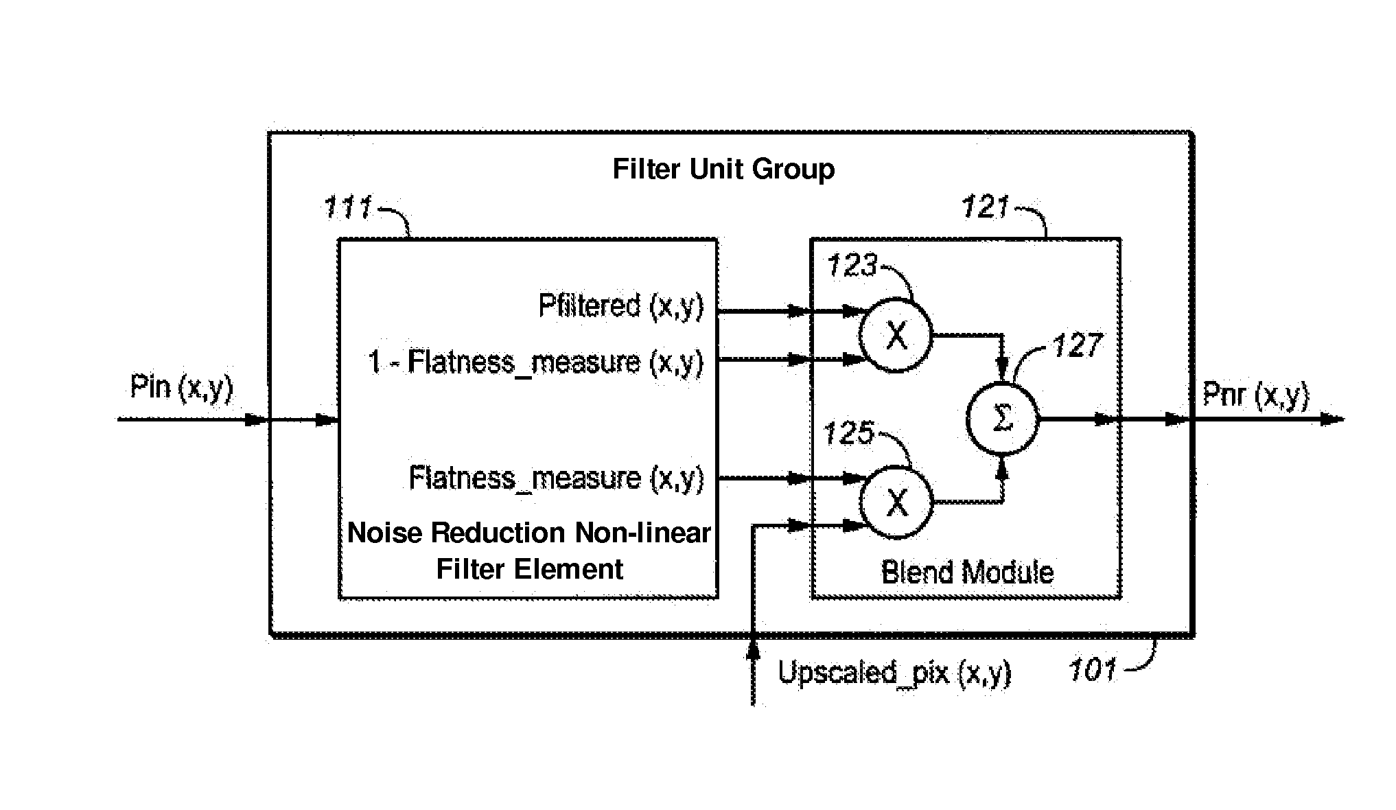
[0008]FIG. 1 illustrates an example of a filter unit group of the present invention;

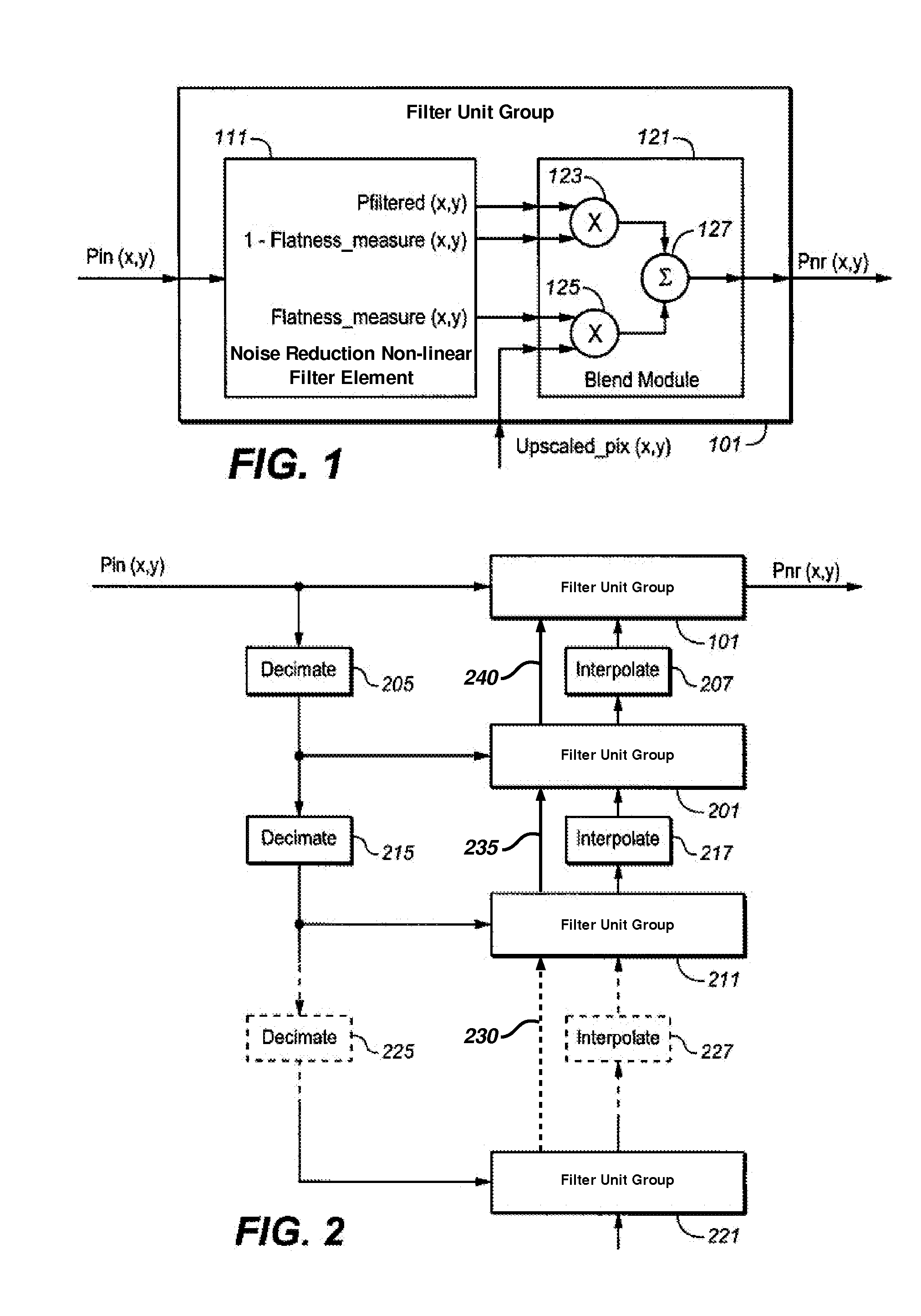
[0009]FIG. 2 is a block diagram of one configuration (“increasing depth” mode) of filter unit groups;

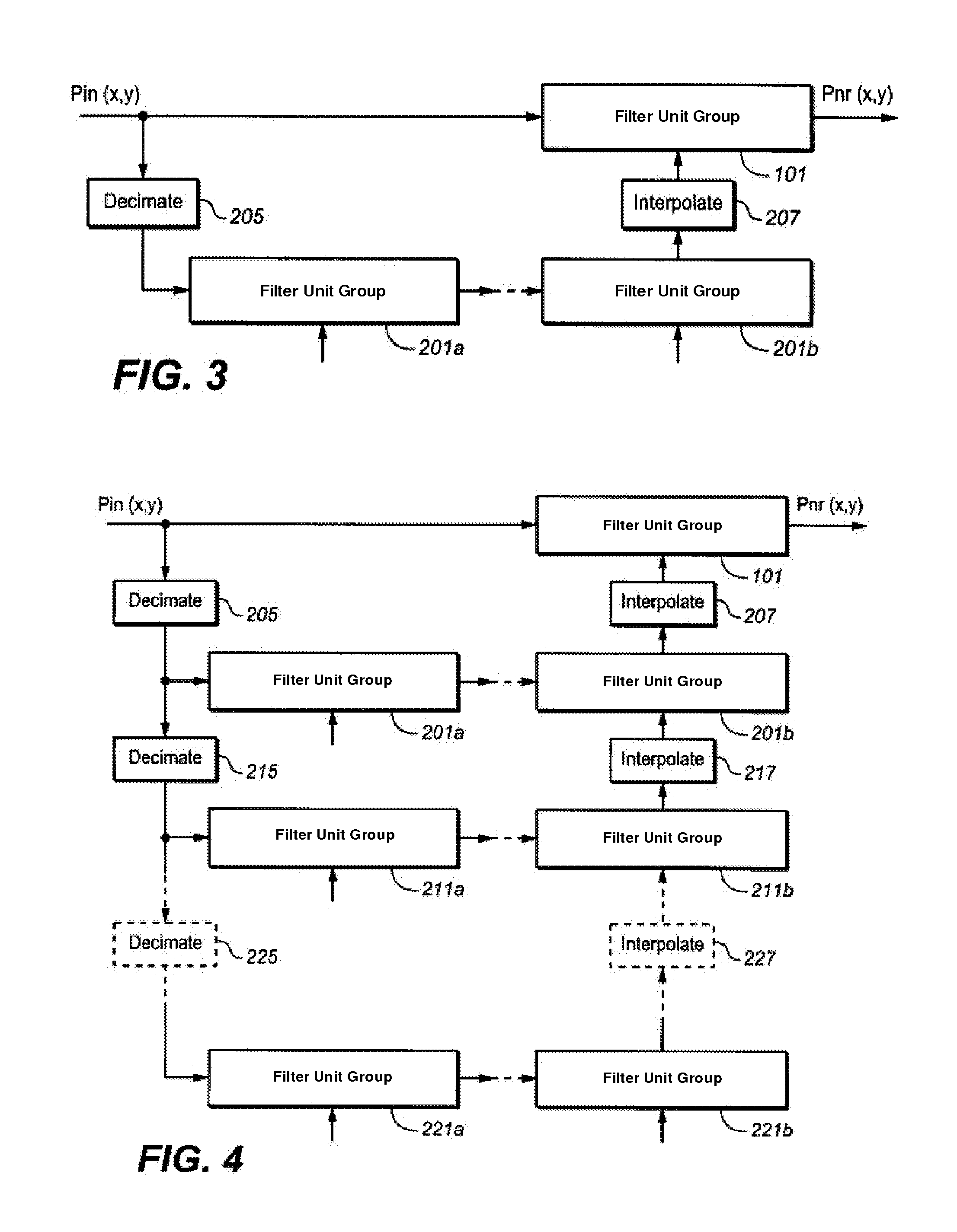
[0010]FIG. 3 is a block diagram of a second configuration (“increasing width” mode) of filter unit groups;

[0011]FIG. 4 shows a generalized filter array combining the width and depth modes; and

[0012]FIG. 5 illustrates an example of an extended filter unit group of the present invention.

DETAILED DESCRIPTION OF ILLUSTRATIVE EMBODIMENTS

Overview

[0013]In order to achieve the desired results, illustrative embodiments described herein employ a plurality of small noise reduction non-linear filters working on decimated (downscaled) representations of the image being acquired and performing in concert to achieve performance equivalent to a much larger filter. These offer a comprehensive solution, which can be implemented in hardware (HW) in the illustrative embodiments, and which includes de...


PUM


Abstract

A noise reduction apparatus for digital cameras is presented that includes groups of one or more connected non-linear filter units. Each of the filter unit groups are driven by decimated input image data at a different level of decimation and the output of at least one of these filter unit groups serves as one of a plurality of inputs to another filter unit group driven at a different decimation level. Filtered image data from one or more filter unit groups is adaptively combined in response to one or more image metrics related to one or more local regional image characteristics.

Description

CROSS-REFERENCE TO RELATED APPLICATIONS[0001]This is a continuation-in-part of co-pending U.S. patent application Ser. No. 13 / 160,775, filed on Jun. 15, 2011 (to be abandoned), which is a continuation of U.S. patent application Ser. No. 11 / 754,202, filed on May 25, 2007 (now U.S. Pat. No. 7,983,503), which are incorporated herein by reference.BACKGROUND[0002]This application relates to image processing in digital cameras and other electronic digital image acquisition devices, and particularly to techniques for improving noise reduction techniques for such images.[0003]Images obtained by digital cameras and other imaging systems contain random noise, which typically grows stronger as the ISO sensitivity grows higher. Noise reduction in digital cameras is becoming increasingly important and problematic because of several trends in the digital camera market which result in lower Signal to Noise Ratios (SNR), including the increasing of sensor resolution by reducing the pixel size and t...

Claims


Application Information

Patent Timeline
Patent Type & Authority Applications(United States)
IPC IPC(8): H04N9/64
CPCG06T5/002H04N5/217H04N9/646G06T5/00H04N5/357H04N5/23229H04N23/81H04N23/80H04N25/60
Inventor VAKRAT, DUDIKOREM, NOAMPINTO, VICTOR
Owner QUALCOMM INC
Why Eureka
Try Eureka