

Carbide end mill and cutting method using the end mill
Active Publication Date: 2012-01-26
HITACHI TOOL ENG LTD
View PDF14 Cites 36 Cited by
- Summary
- Abstract
- Description
- Claims
- Application Information
AI Technical Summary
Benefits of technology
[0063]In the case where the carbide end mill of the present invention is required to remove chips in a larger amount per unit time as compared with conventional end mills, as described above, the gash shape of the end cutting edges is optimized as described above in the present invention. Through formation of gashes having a gash shape defined in the present invention, the following advantageous effects can be yielded. Longitudinal-feed cutting, lateral-feed cutting, and oblique cutting can be performed by use of a single carbide end mill having wavy peripheral cutting edges or peripheral cutting edges having phase-shifted nicks. Chips removed from the end cutting edges at the time of longitudinal-feed cutting or oblique cutting can be treated satisfactorily. The gash portions are strong enough to endure high-speed, lateral or oblique cutting. Further, chattering vibration can be minimized.
[0064]The carbide end mill of the present invention has peripheral cutting edges whose phases are deviated from the respective reference phases of the reference peripheral cutting edge, wherein the distance of the reference phase is an amount corresponding to a value obtained by dividing a pitch of the nick of the reference peripheral cutting edge by the number of the cutting edges—and also has the above-described gash shape in regions from the cutting faces of the end cutting edges to the peripheral cutting edges. Therefore, the carbide end mill of the present invention can efficiently cut structural steel, structural alloy steel, die steel for cold or hot working, stainless steel, titanium alloy, and super-heat-resistant alloy.
[0065]That is, the carbide end mill of the present invention is intended to machine a workpiece formed of structural steel, structural alloy steel, die steel for cold or hot working, stainless steel, titanium alloy, or super-heat-resistant alloy.
[0066]Next, suitable hard coats for the carbide end mill of the present invention and which enhances the characteristics thereof will be described. In the present invention, the shape of the carbide end mill is novel enough to enable high-speed cutting. Therefore, a hard coat is not necessarily required. However, use of an optimal hard coat is important so as to stabilize and extend the service life of the end mill of the present invention when the end mill is used for high-speed cutting.
[0067]Various hard coats have been developed so as to improve the performances and service lives of carbide end mills, and the hard coat proposed by the applicant of the present invention and disclosed in Patent Document 7 has been put to practical use. Since end mills are required to have higher oxidation resistance and higher wear resistance so as to cope with an increase in cutting speed, measures for enhancing oxidation resistance and wear resistance must be taken. When the present inventors actually used the above-described carbide end mill having a novel shape for rough machining, they found a remarkable increase in oxidation and wear of the peripheral cutting edges, which are peculiar to high-speed cutting. The present invention has been accomplished as measures against such oxidation and wear.
[0068]That is, the carbide end mill with hard coat according to the present invention is characterized in that a hard coat which can endure high-speed cutting is laminated on at least the wavy peripheral cutting edges or nicked peripheral cutting edges having a novel shape as described earlier.
Problems solved by technology
However, in such a case, a problem of chattering vibration often arises.
However, when an equal separation end mill is used, resonance is apt to occur during machining, resulting in generation of chattering vibration.
But such an end mill involves increased production cost and time in the course of its production.
However, when high-efficiency machining is performed by increasing the depth of cut, there often arises a problem in that chipping or fracture occurs, particularly, at nick portions due to chattering vibration.
However, it is difficult to perform these cuttings by using a single end mill.
Method used
View moreImage
Smart ImageViewing Examples

Examples
examples
[0234]The present invention will next be described in more detail by way of examples, which should not be construed as limiting the invention thereto.
[0235]Examples are classified into five groups according to their purposes; specifically, the following Example A, Example B, Example C, Example D, and Example E:
example a
in which the optimal shape of peripheral cutting edges of the end mill of the present invention is confirmed (Examples A1 to A6);
example b
in which the shape of nicks is optimized in the end mill of the present invention (Examples B1 and B2);
Login to View More PUM
 Abstract
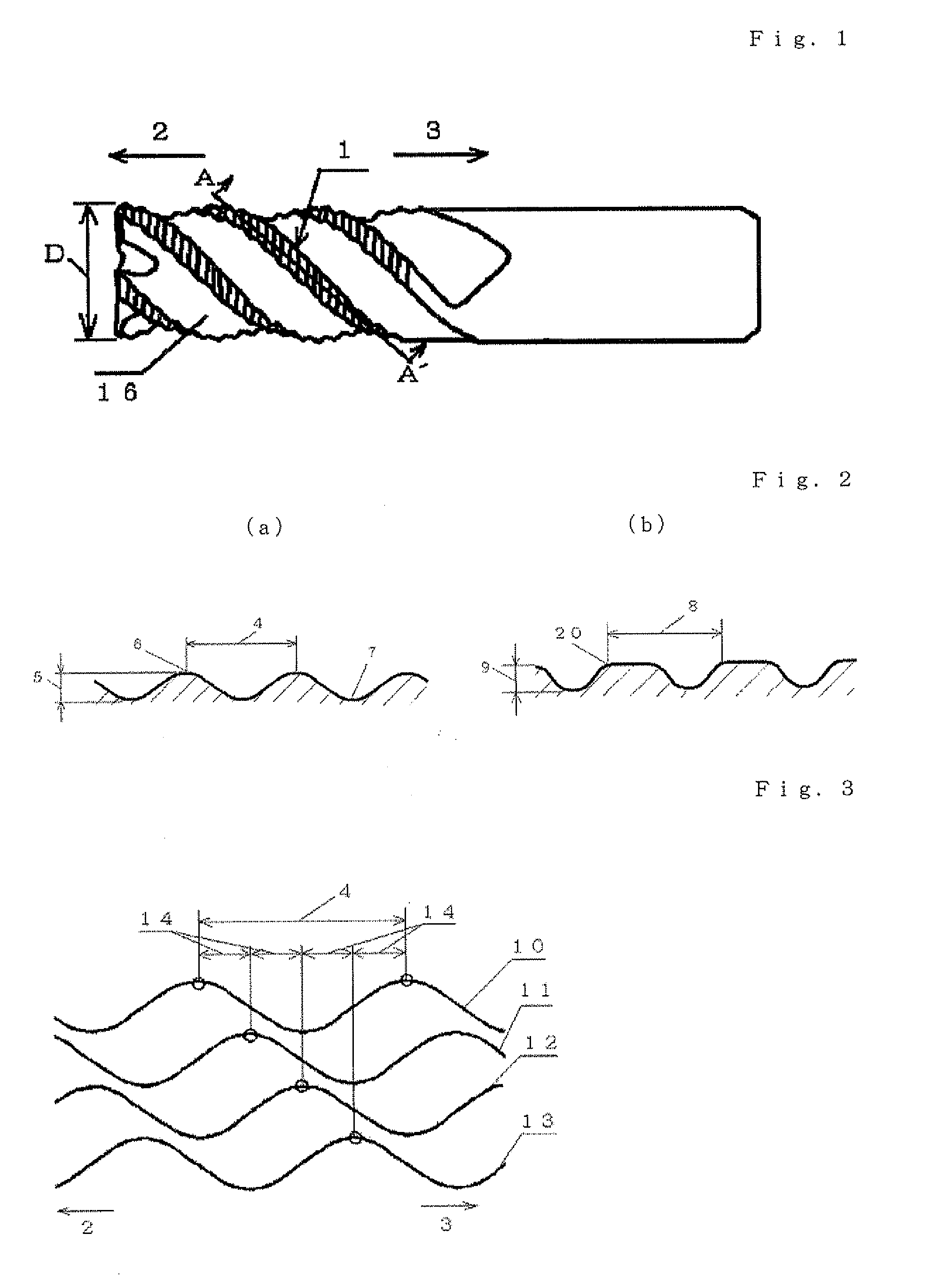
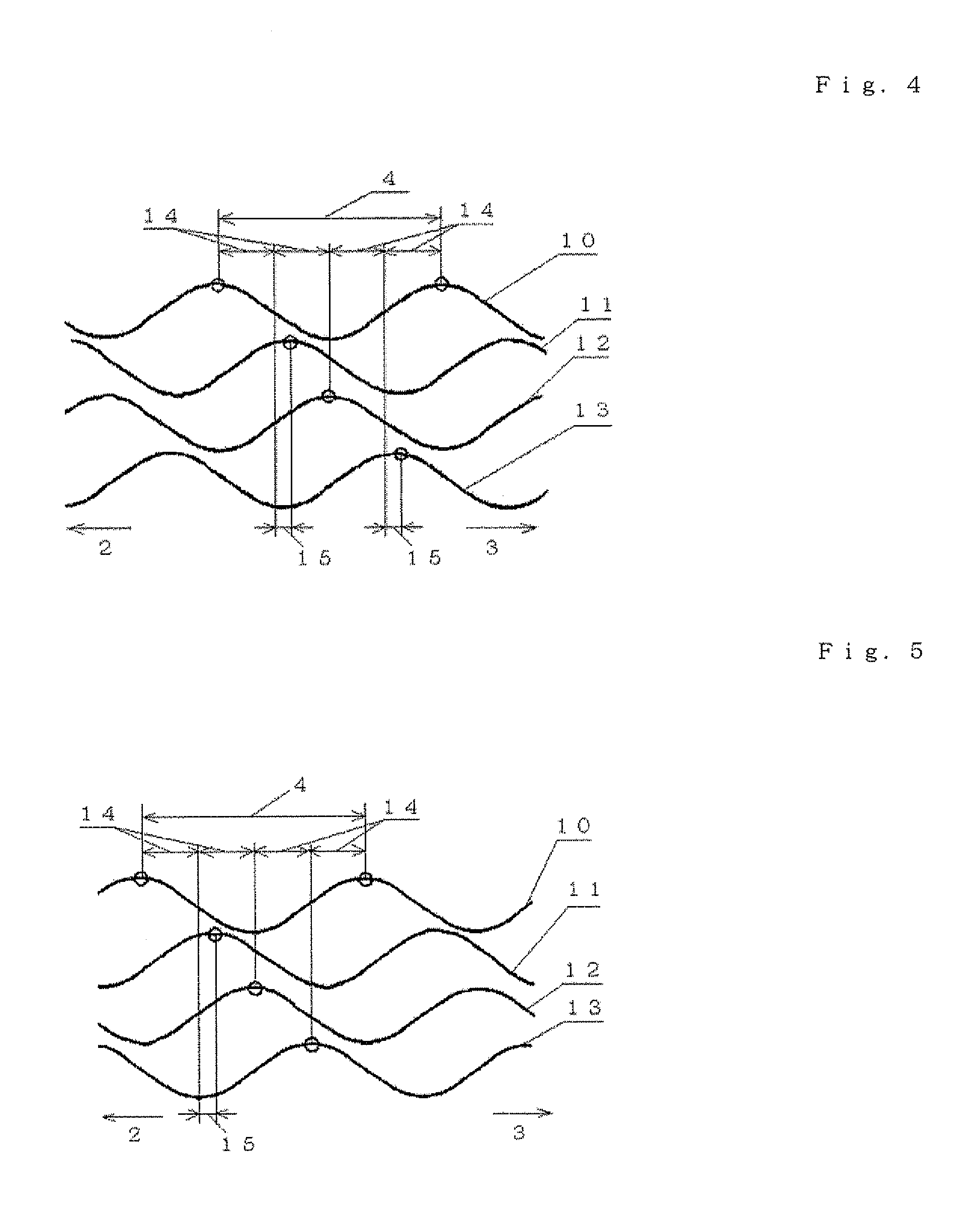
Provided is a long life carbide end mill which can perform stable cutting in high-efficiency machining such as die machining and parts machining. A cutting method using such an end mill is also provided. When a certain wavy or nicked peripheral cutting edge is considered a reference peripheral cutting edge with reference phases in a pitch of the reference peripheral cutting edge, wherein the distance of each reference phase is an amount corresponding to a value obtained by dividing the pitch of the nicks or waveform of each peripheral cutting edge by the number of the cutting edges; and the phase of at least one of the remaining peripheral cutting edges is deviated in the direction of the tool axis from the corresponding reference phase by an amount corresponding to 5% or less (excluding 0%) of the pitch.
Description
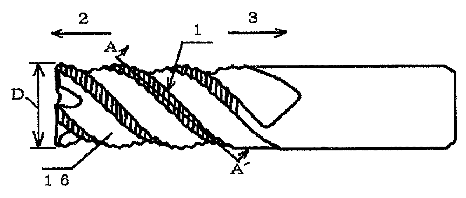
TECHNICAL FIELD[0001]The present invention relates to a carbide end mill used for cutting in a range from rough cutting to semi-finishing cutting, and to a cutting method performed by use of the end mill.[0002]An object of the present invention is to provide a versatile carbide end mill which can solely and multifunctionally perform, longitudinal-feed machining, lateral-feed machining, and oblique machining which is combination of longitudinal-feed machining and lateral-feed machining, in machining steps from a rough cutting step to a semi-finishing cutting at high speed. These machinings described above are performed respectively by selecting different type of end mill on prior art. Another object of the present invention is to provide a cutting method which is performed by making use of such an end mill.[0003]A conventional typical end mill for rough cutting, to which the present invention can be applied, is made of high-speed tool steel or carbide as the base material. Each of pe...
Claims
Login to View More Application Information
Patent Timeline
 IPC IPC(8): B23C5/10B23C5/20
CPCB23C5/003B23C5/10B23C2210/086B23C2210/088B23C2210/287Y10T407/1948Y10T407/1966Y10T407/1962Y10T407/1946Y10T407/1924B23C2250/16B23C5/16B23C5/02
InventorMAEDA, KATSUTOSHIHAN, GANG
OwnerHITACHI TOOL ENG LTD