Permanent Magnet Rotating Machine

a permanent magnet, rotating machine technology, applied in the direction of mechanical energy handling, magnetic circuit rotating parts, magnetic circuit shape/form/construction, etc., can solve problems such as electrical characteristics that may be worsened, and achieve the effects of reducing harmonic components, preventing magnetic flux concentration, and increasing efficiency

Inactive Publication Date: 2012-02-09
HITACHI LTD
View PDF8 Cites 29 Cited by
  • Summary
  • Abstract
  • Description
  • Claims
  • Application Information

AI Technical Summary

Benefits of technology

[0009]In Patent Document 1 above, to increase efficiency, gaps between the rotator and stator are increased near parts between magnetic poles, in comparison wit

Problems solved by technology

Furthermore, the magnet insertion slot is shaped so that the corners of the magnet are not brought into contact, the cross sectional area of the iron core (bridge on the external diameter side) between the end of the magnet insertion slot on the external diameter side

Method used


Image

  • Permanent Magnet Rotating Machine
  • Permanent Magnet Rotating Machine
  • Permanent Magnet Rotating Machine

Examples


first embodiment

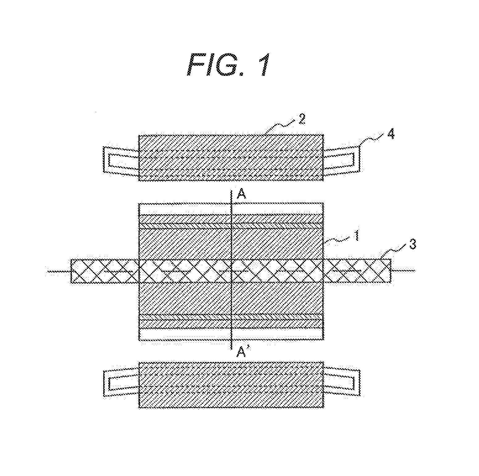
[0043]FIG. 1 schematically shows the structure of a permanent magnet rotating machine with an output power of 1 to 3 MW that will be mounted in an electrical train as a railroad generator and will operate at a rotational speed of 500 min−1 to 2000 min−1.

[0044]As shown in the drawing, a rotor 1, in which permanent magnets are provided, is attached to a shaft 3, and a stator 2 is oppositely disposed with a predetermined distance left between the rotor 1 and stator 2. A coil 4 is embedded in the stator 2.

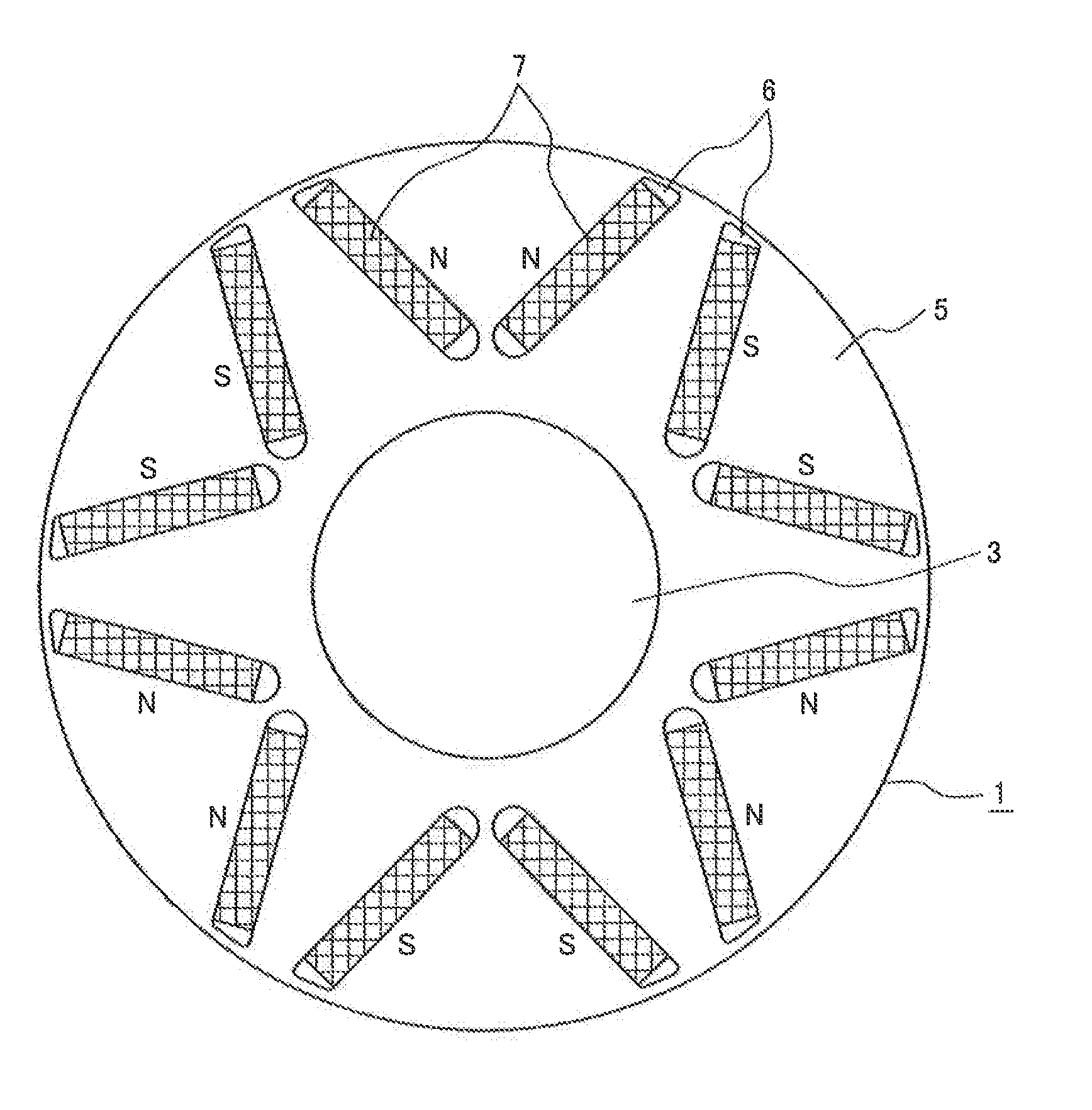
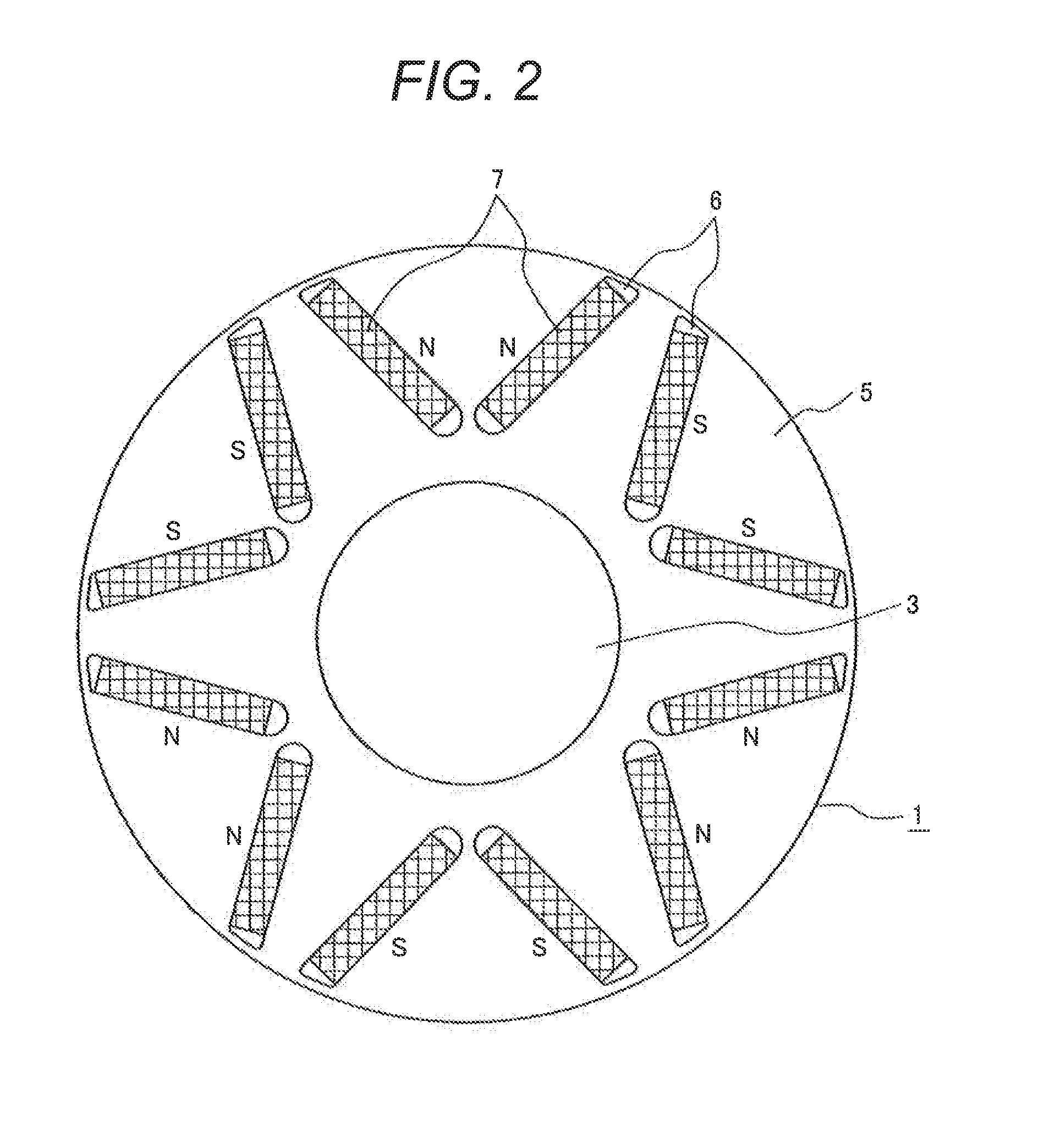
[0045]As shown in FIG. 2, the rotor 1 includes a rotor iron core 5, in which magnet insertion slots 6 are formed so that each two magnet insertion slots 6 with the same pole form a substantially V shape when viewed from the outer circumference of the rotor 1. Specifically, the two magnet insertion slots 6 formed in one pole are formed in a substantially V shape in which the circumferential distance therebetween becomes larger as the two magnet insertion slots extend toward the outer ci...

second embodiment

[0067]FIG. 11 shows the rotor of a six-pole permanent magnet rotating machine according to a second embodiment of the present invention. As shown in the drawing, the permanent magnet rotor includes a rotor iron core 16, in which magnet insertion slots 17 are formed so that two magnet insertion slots 17 form a substantially V shape for each pole when viewed from the outer circumference of the rotor, and a flat-plate magnet 7 is embedded in each magnet insertion slot 17.

[0068]FIG. 12 is an enlarged view of the magnet insertion slot 17. In this embodiment, to form a step, the width W of an end 8 of the magnet insertion slot 17 is smaller than the width Wg of a magnet insertion portion.

[0069]In this embodiment, a range in which the flat-plate magnet 7 moves in the width direction is narrowed by the step. Accordingly, when the rotor rotates, movement of the flat-plate magnet 7 in the magnet insertion slot 17 can be suppressed, preventing the magnet from being damaged due to vibration and...

third embodiment

[0075]In addition to the structures in the first and second embodiments, permanent magnets 22 disposed in a rotor iron core 21 are divided in the width direction as shown in FIG. 14, in this embodiment. This enables the eddy current generated in each permanent magnet 22 to be reduced, and thereby the efficiency can be improved and the temperature in the permanent magnet rotating machine can be reduced. Even if the permanent magnet 22 is divided in the axial direction, the same effect can be obtained.


PUM


Abstract

A permanent magnet rotating machine has a stator, in which armature windings are formed in a plurality of slots formed in a stator iron core, and also has a rotor, in which two magnet insertion slots are formed for each pole in a rotor iron core in a V shape when viewed from the outer circumference of the rotor and one permanent magnet is embedded in each magnet insertion slot with polarity alternating for each pole; a wall at one end of the magnet insertion slot on the external diameter side of the rotor is formed with three arcs having different curvatures, one of the three arcs being parallel to the outer circumference of the rotor, and a wall at the other end of the magnet insertion slot on the internal diameter side of the rotor is formed in an arc shape.

Description

CLAIM OF PRIORITY[0001]The present application claims priority from Japanese application serial No. 2010-178298, filed on Aug. 9, 2010, the content of which is hereby incorporated by reference into this application.FIELD OF THE INVENTION[0002]The present invention relates to a permanent magnet rotating machine and, more particularly, to a permanent magnet rotating machine suitable as a rotating machine having a medium or large capacity such as a wind turbine generator or a generator mounted on a vehicle.BACKGROUND OF THE INVENTION[0003]As rotating machines have been compact and highly efficient, permanent magnet rotating machines have been used in various fields in recent years. When permanent magnets are used, however, there is a problem in that not only electrical characteristics but also strength characteristics are restricted.[0004]In particular, rotating machines with an output capacity in the several megawatt class, such as generators mounted in railroad vehicles and wind turb...

Claims


Application Information

Patent Timeline
IPC IPC(8): H02K1/28H02K1/32
CPCH02K1/2766Y02E10/725H02K16/00H02K7/1838Y02E10/72
Inventor HORI, MASAHIROKORI, DAISUKEKOMURA, AKIYOSHIMASUDA, SEIKICHIKIMURA, MAMORUOBATA, NOBUHIKOKOIZUMI, TAKAYUKI
Owner HITACHI LTD
Why Eureka
Try Eureka