Method and apparatus for determining the location of the ocular pivot point

a technology of ocular pivot point and location, applied in the field of methods for determining the location of the ocular pivot point, can solve the problems of many assumptions that do not sufficiently correspond to the actual circumstances, no reference, and the video centering system is so far not in a position to optimize the spectacle lens. , to achieve the effect of improving the determination of values

Active Publication Date: 2012-02-09
CARL ZEISS VISION INT GMBH
View PDF4 Cites 13 Cited by
  • Summary
  • Abstract
  • Description
  • Claims
  • Application Information

AI Technical Summary

Benefits of technology

[0063]These above-specified measures afford the advantage that the determination of the values is improved by virtue of the fact that these values are determined in a fashion spatially referred to one another, that is to say, referred to a specific axis or to the pupil center.
[0064]The phase errors can, for example, be measured by means of a wavefront refractor by using the Hartmann-Shack method. A mea

Problems solved by technology

However, these video centering systems are so far not in a position to be able to optimize the spectacle lens with the aid of the location of the ocular pivot point in a sufficiently exact way.
However, in this case many assumptions are made that do not sufficiently correspond to the actual circumstances.
However, this is not the case in reality, because both the curvature of the cornea and the eye lens as well as the eye length increase very independently of one another and/or develop differently.
It is disa

Method used


Image

  • Method and apparatus for determining the location of the ocular pivot point
  • Method and apparatus for determining the location of the ocular pivot point
  • Method and apparatus for determining the location of the ocular pivot point

Examples


first embodiment

[0113]In the case of a first embodiment of an inventive method, the location of the ocular pivot point ADL is determined on the basis of an eye model and an estimate of the eye length LA. An inventive device 120 for carrying out the method is shown in FIG. 11. The method comprises the steps set forth below.

[0114]In a first step 1a), a unit 122, specifically a suitable scanner, is used to determine the topography of the cornea 14, and from that the mean curvature KH of the cornea 14. It is possible during this measurement for the location of the center of the pupil 17 to be determined at the same time in addition to the position of the vertex of the cornea 14.

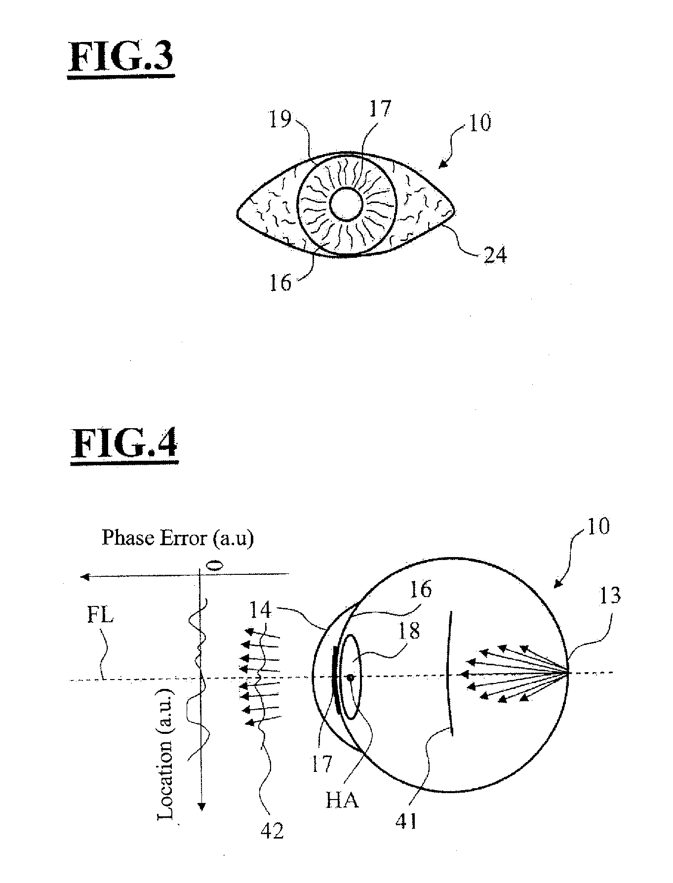
[0115]In a second step 1b), the phase errors and the mean value of the phase error PF of the eye 10 are determined. Use is made for this purpose of, for example, a wavefront autorefractor 124 of known design, which determines the distribution of the phase errors over the entire opening of the pupil 17 of the eye 10, as is illust...

second embodiment

[0125]In accordance with a second embodiment of an inventive method, it is also possible to detect the position and / or the shape of a characteristic part of the eye in at least two viewing directions, and to determine therefrom, in turn, the position of at least one characteristic axis of the eye for these two viewing directions, and to determine the location of the ocular pivot point with the aid of this / these characteristic axis / axes of the eye for the two viewing directions.

[0126]The location of the ocular pivot point determined in such a way can then be used, in turn, as input parameter in the calculation of a spectacle lens optimized in customized fashion.

[0127]The first variant, specifically the determination of the location of the ocular pivot point from the position of a characteristic part of the eye takes place as set forth below.

[0128]The test person is charged with looking at a specific fixation target. A calibrated photographic system is used to record the eye for this ...

third embodiment

[0136]In the case of a third embodiment of an inventive method, the surface of the cornea 14 is measured in three dimensions in a first step 3a), for example, given that the test person is looking in a direction straight ahead. This can be done, for example, by means of a unit such as marketed by Carl Zeiss Vision GmbH under the designation of “iProfiler”. FIG. 13 outlines an arrangement 140 for carrying out the method. The “iProfiler” is denoted by the reference numeral 141 in FIG. 13.

[0137]FIG. 6 shows an exemplary illustration of the points that are measured on the cornea 14 in the case of a look directed straight ahead. The Z-axis, directed upwardly, coincides with this viewing direction.

[0138]In a second step 3b), the surface of the cornea 14 determined in the first step is described, for example, in a computer 143 by a three-dimensional mathematical formula.

[0139]The customary mathematical methods can be used to determine this formula. An example of this is the approximation o...


PUM


Abstract

The invention relates to a method for determining the location of the ocular pivot point (ADL) in an eye (10) of a test person. In the method, the mean curvature (KH) of the cornea (14) of the eye (10) is determined. The mean phase error (PF) of the eye (10) is determined as is the eye length (LA) from the mean curvature (KH) and the mean phase error (PF). The location of the ocular pivot point (ADL) is determined from the eye length (LA).

Description

CROSS REFERENCE TO RELATED APPLICATIONS[0001]This application is a continuation application of international patent application PCT / EP 2010 / 000698, filed Feb. 4, 2010, designating the United States and claiming priority from German application 10 2009 010 467.4, filed Feb. 26, 2009, and the entire content of both applications is incorporated herein by reference.FIELD OF THE INVENTION[0002]The invention relates to methods for determining the location of the ocular pivot point in an eye of a test person.[0003]The invention further relates to methods for optimizing a spectacle lens customized for an eye in which the location of the ocular pivot point is determined and used as input parameter.[0004]Finally, the invention relates to a method for determining at least two optical parameters of an eye having a reference structure wherein the eye is recorded photographically by separate recording units to determine corresponding ones of the parameters.[0005]The invention further relates to a...

Claims


Application Information

Patent Timeline
IPC IPC(8): A61B3/107A61B3/14
CPCA61B3/1005A61B3/111A61B3/113G02C7/027G02C13/005
Inventor KRATZER, TIMOCABEZA-GUILLEN, JES S-MIGUELKELCH, GERHARD
Owner CARL ZEISS VISION INT GMBH
Why Eureka
Try Eureka