Recording apparatus

a recording device and recording medium technology, applied in the direction of printing, other printing devices, etc., can solve the problems of deteriorating printing quality in some cases, and achieve the effect of enhancing the planarity of the recording medium

Active Publication Date: 2012-03-22
SEIKO EPSON CORP
View PDF1 Cites 24 Cited by
  • Summary
  • Abstract
  • Description
  • Claims
  • Application Information

AI Technical Summary

Benefits of technology

[0025]With this configuration, according to the aspect of the invention, curls of the recording medium which is unrolled and extended f...

Problems solved by technology

Therefore, even if the planarity of the recording medi...

Method used


Image

  • Recording apparatus
  • Recording apparatus
  • Recording apparatus

Examples


Embodiment Construction

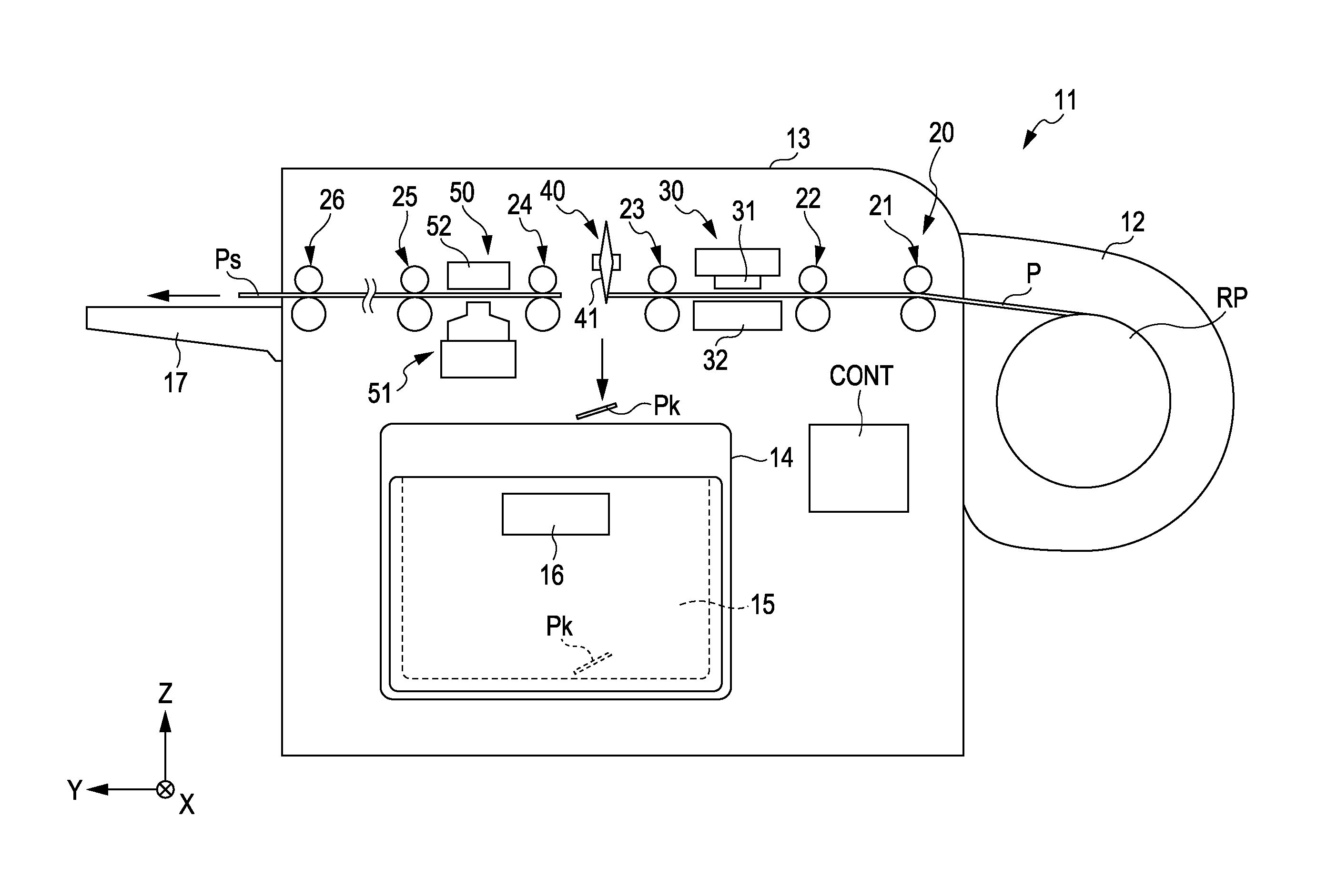
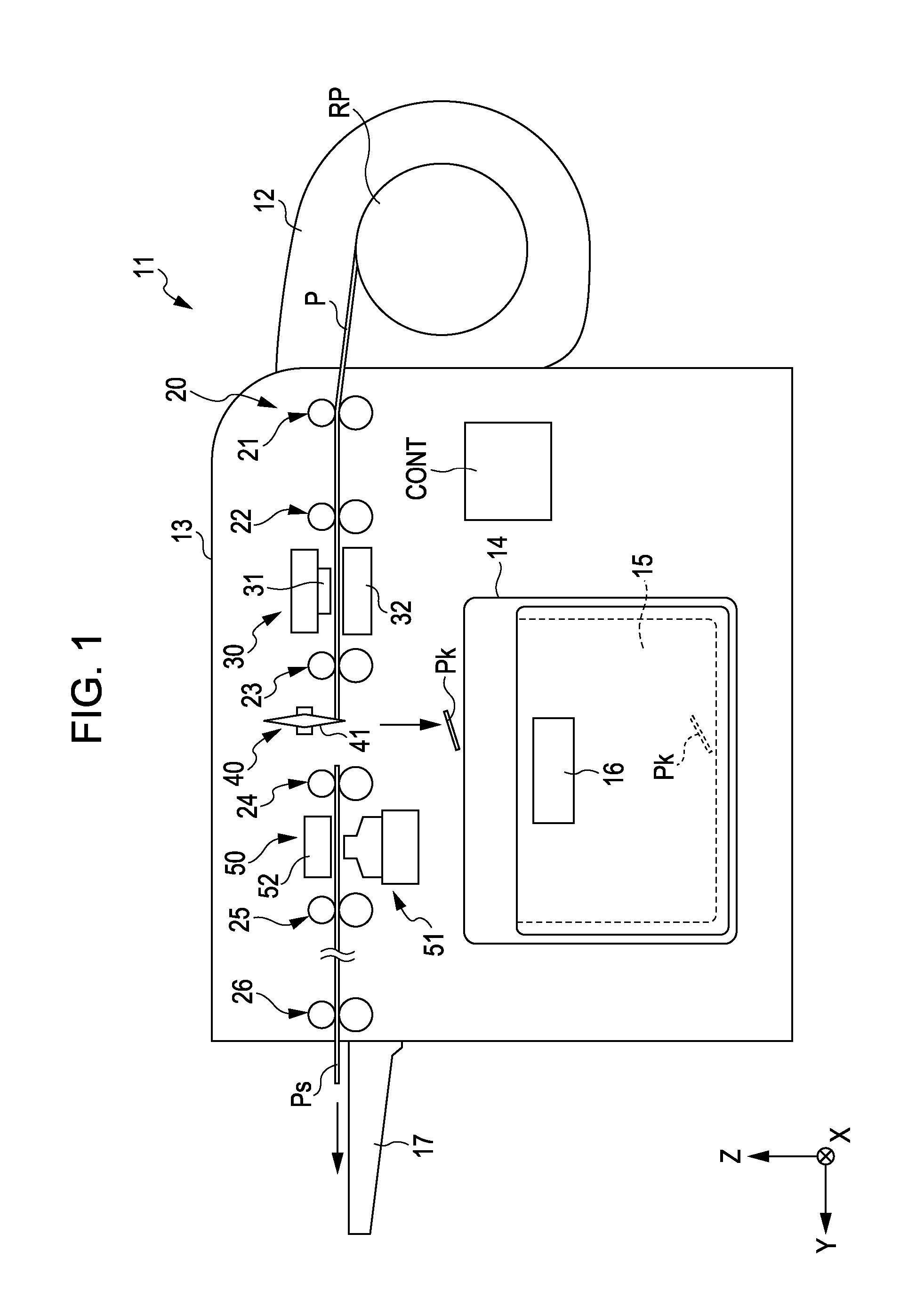
[0035]Hereinafter, an embodiment of a recording apparatus according to the invention is described with reference to drawings. It is to be noted that in the drawings used in the following description, an XYZ orthogonal coordinate system is set and a positional relationship of each member is described with reference to the XYZ orthogonal coordinate system in some case. Note that a predetermined direction in a horizontal plane is assumed to an X-axis direction (width direction), a direction perpendicular to the X-axis direction in the horizontal plane is assumed to a Y-axis direction (transportation direction), and a direction (vertical direction) perpendicular to the X-axis direction and the Y-axis direction is assumed to a Z-axis direction.

[0036]In the embodiment, an ink jet printer (hereinafter, simply referred to as “printer”) as a recording apparatus is described as an example.

[0037]FIG. 1 is a schematic configuration view illustrating a printer 11 according to an embodiment of th...


PUM


Abstract

A recording apparatus includes a supporting member on which a plurality of suction holes for sucking a recording medium are formed on a supporting face for supporting the recording medium, a transportation device which transports the recording medium along the supporting face, a recording head which ejects fluid on the recording medium supported by the supporting face so as to perform printing, and a control device which makes the recording head execute the printing when a front end of the recording medium in the transportation direction reaches to a position at which the front end of the recording medium covers the suction holes formed at downstream-most positions in the transportation direction on the supporting face.

Description

[0001]The entire disclosure of Japanese Patent Application No: 2010-209083, filed Sep. 17, 2010 is expressly incorporated by reference herein.BACKGROUND[0002]1. Technical Field[0003]The present invention relates to a recording apparatus.[0004]2. Related Art[0005]An ink jet printer has been disclosed as a recording apparatus in JP-A-2003-211749.[0006]The ink jet printer uses a roll paper as a recording medium and includes a plurality of suction holes on a platen in order to keep planarity of the roll paper on a printing region printed by an ink jet head. The plurality of suction holes are gradually made smaller as the suction holes are away from the upstream side to the downstream side in a transportation direction of the recording medium. Further, the plurality of suction holes are gradually made smaller as the suction holes are away from the vicinity of a center position in a width direction of the recording medium to outer sides in the width direction.[0007]With this configuration...

Claims


Application Information

Patent Timeline
IPC IPC(8): B41J29/38
CPCB41J11/663B41J11/0085
Inventor HIGUCHI, KOJI
Owner SEIKO EPSON CORP
Why Eureka
Try Eureka