Supporting arch structure construction method

a technology of supporting structure and supporting structure, applied in the direction of bridges, structural elements, building components, etc., can solve the problem of only temporarily using the supporting structur

Inactive Publication Date: 2012-04-26
EURON COMMUNITY EC
View PDF16 Cites 11 Cited by
  • Summary
  • Abstract
  • Description
  • Claims
  • Application Information

AI Technical Summary

Benefits of technology

[0024]Hence, given an initially straight, horizontal frame structure having a length of 100 m between the points of application of the compressive forces at the ends and assuming a perfectly parabolic shape of the resulting arch, a relative displacement of

Problems solved by technology

However, it is also possible that the supporting structure is only

Method used


Image

  • Supporting arch structure construction method
  • Supporting arch structure construction method
  • Supporting arch structure construction method

Examples


Embodiment Construction

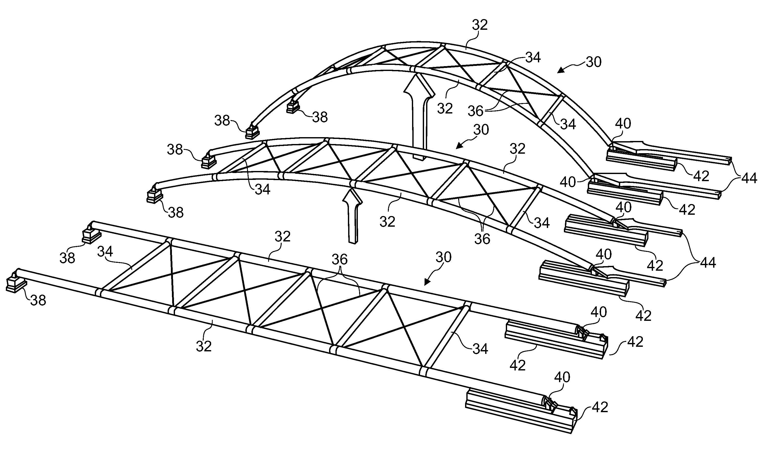
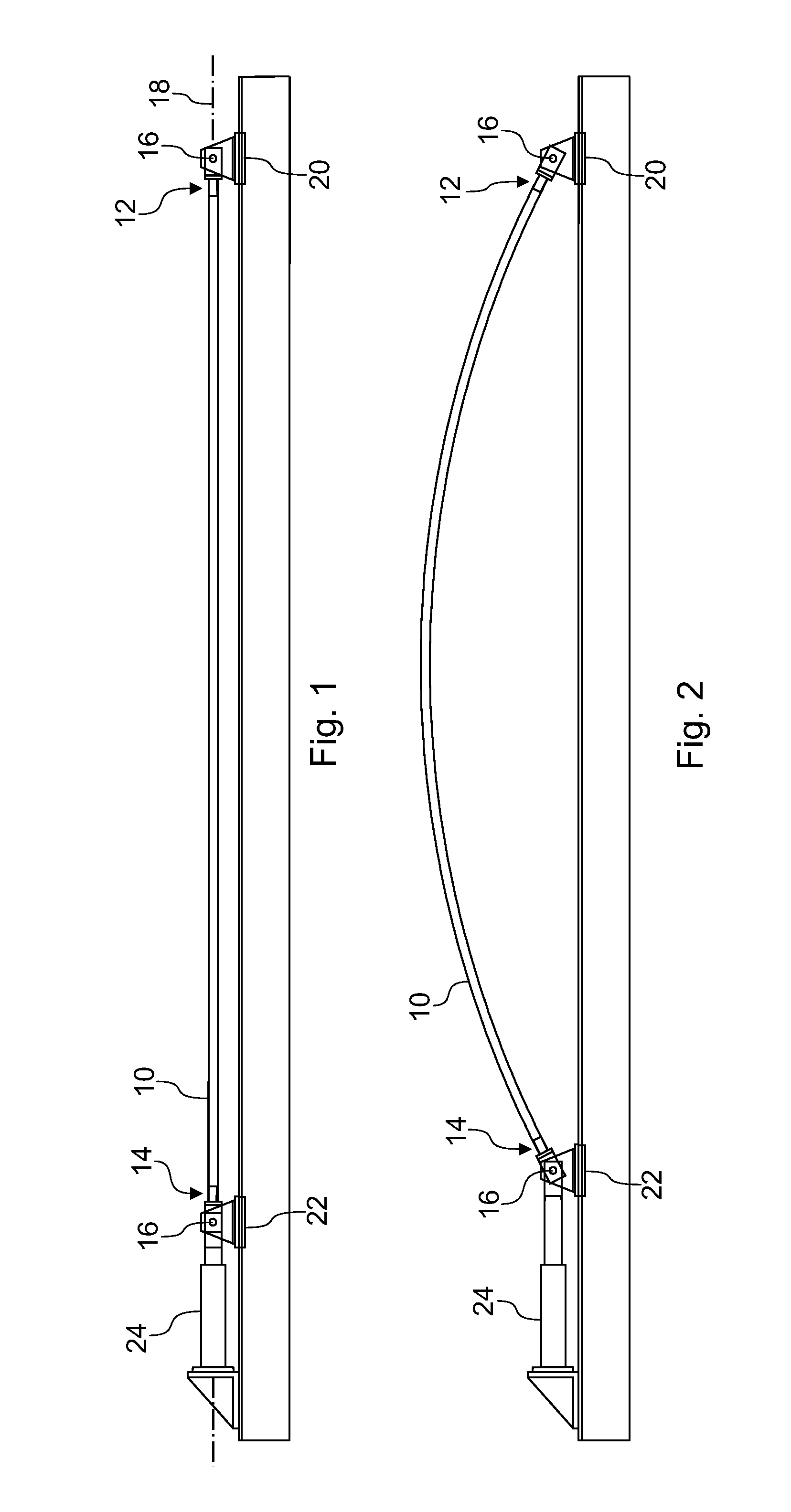
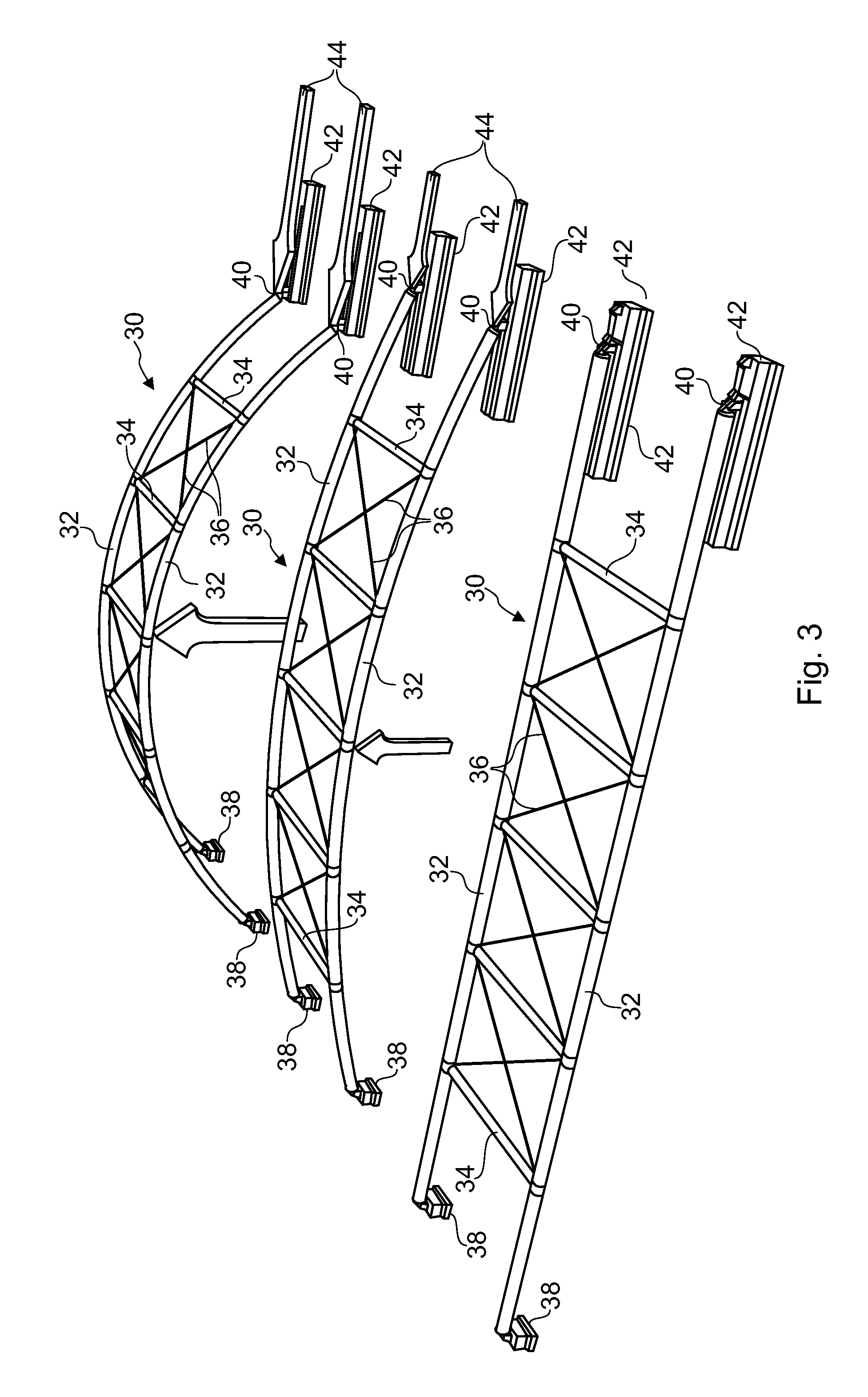
[0038]FIGS. 1 and 2 illustrates the general concept underlying the method of constructing an arched supporting structure. An initially straight beam 10 of tubular (rectangular, round, trapezoidal or other) cross section is mounted pivotally supported at its ends 12, 14. The pivot axes 16 are parallel to one another and perpendicular to the longitudinal axis 18 of the beam. (FIGS. 1 and 2 show the longitudinal axis 18 and the pivot axes 16 to be horizontal; however, this is not necessary in general.) A stationary swivel 20 pivotally supports the first end 12 of the beam 10. The stationary swivel 20 is firmly anchored in the ground so as to form a first abutment of the arched supporting structure to be constructed. The second end 14 of the beam 10 is pivotally supported by a movable swivel 22, guided on rails (not shown in FIGS. 1 and 2) extending along the direction of the longitudinal axis 18 of the beam. An actuator 24 (e.g. a hydraulic or other actuator as commonly used in increme...


PUM

PropertyMeasurementUnit
Fractionaaaaaaaaaa
Fractionaaaaaaaaaa
Fractionaaaaaaaaaa

Abstract

In a method of constructing a supporting structure (e.g. of a bridge or the roof of a building) in arched form, an initially straight or pre-curved frame structure, having a first end and a second end opposite to the first end, is pivotally supported at the first and second ends, whereupon the first and second ends are pushed towards one another to achieve a displacement of the first and second ends relative to one another, where the reduction of the distance between the first and second ends causes them to pivot and the frame structure to progressively and flexibly bend, against its resiliency, into a final arched form, the displacement of the first and second ends relative to one another is chosen to amount to at least 1% of the initial distance between the first and second ends, where the first and second ends are then fixed relative to one another in their displaced position so as to preserve the final arched form of the frame structure.

Description

TECHNICAL FIELD[0001]The present invention generally relates to a method of constructing a supporting architectural structure, or structural frame, having the form of an arch. The invention is generically applicable to arch structures in lattice or shell form, in which the main structural forces are resolved into compressive forces, in particular to arch bridges, (e.g. supported deck arch bridges, suspended deck arch bridges, tied arch bridges, etc.) to large arched buildings, tunnels, galleries and temporary supporting structures.BACKGROUND[0002]For the purposes of the present, the terms “supporting structure” and “structural frame” designate the load-resisting sub-system of a construction (architectural structure), i.e. the part of the construction that transfers and possibly absorbs the main load through interconnected structural components or members.[0003]Supporting arch structures, in particular of arch bridges, belong to the oldest engineered forms of construction and have pl...

Claims


Application Information

Patent Timeline
IPC IPC(8): E04B1/32E04G21/02E04B1/38E04B1/344
CPCE01D4/00E01D21/08E01D2101/26E04C5/07E04B1/3205E04C3/44E01D2101/40E04B1/3533
Inventor GUTIERREZ TENREIRO, EUGENIOPOLJANSEK, MARTIN
Owner EURON COMMUNITY EC
Why Eureka
Try Eureka