[0020]It is an object of the present invention to provide an electrical box that is more cost efficient when the electrical box needs to be extended. It is another object of the present invention to provide an electrical box that allows the space around the electrical box and a wall covering opening to be sealed with insulating foam
sealant.
[0021]The present invention achieves these and other objectives by providing an adjustable electrical box with a box extender configured to allow the use of an insulating foam
sealant around the perimeter of the electrical box while minimizing the amount of foam
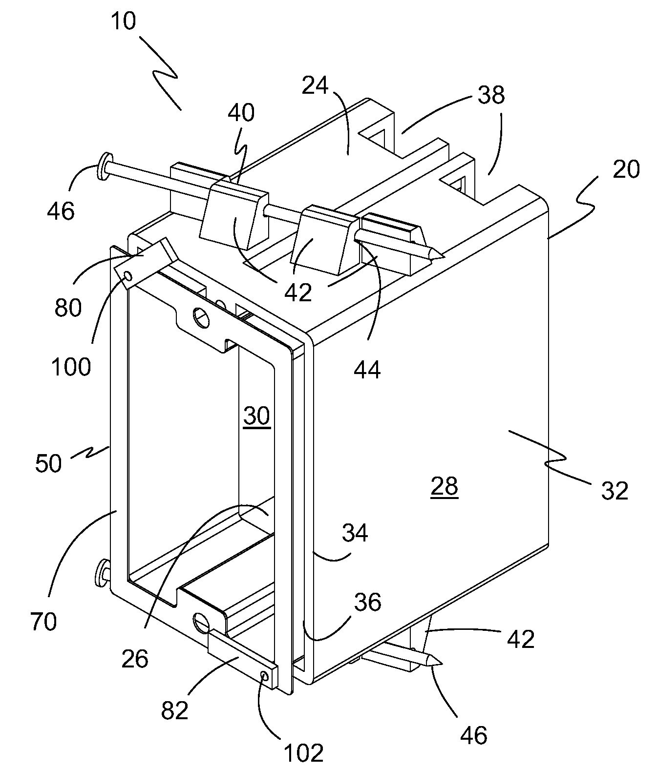
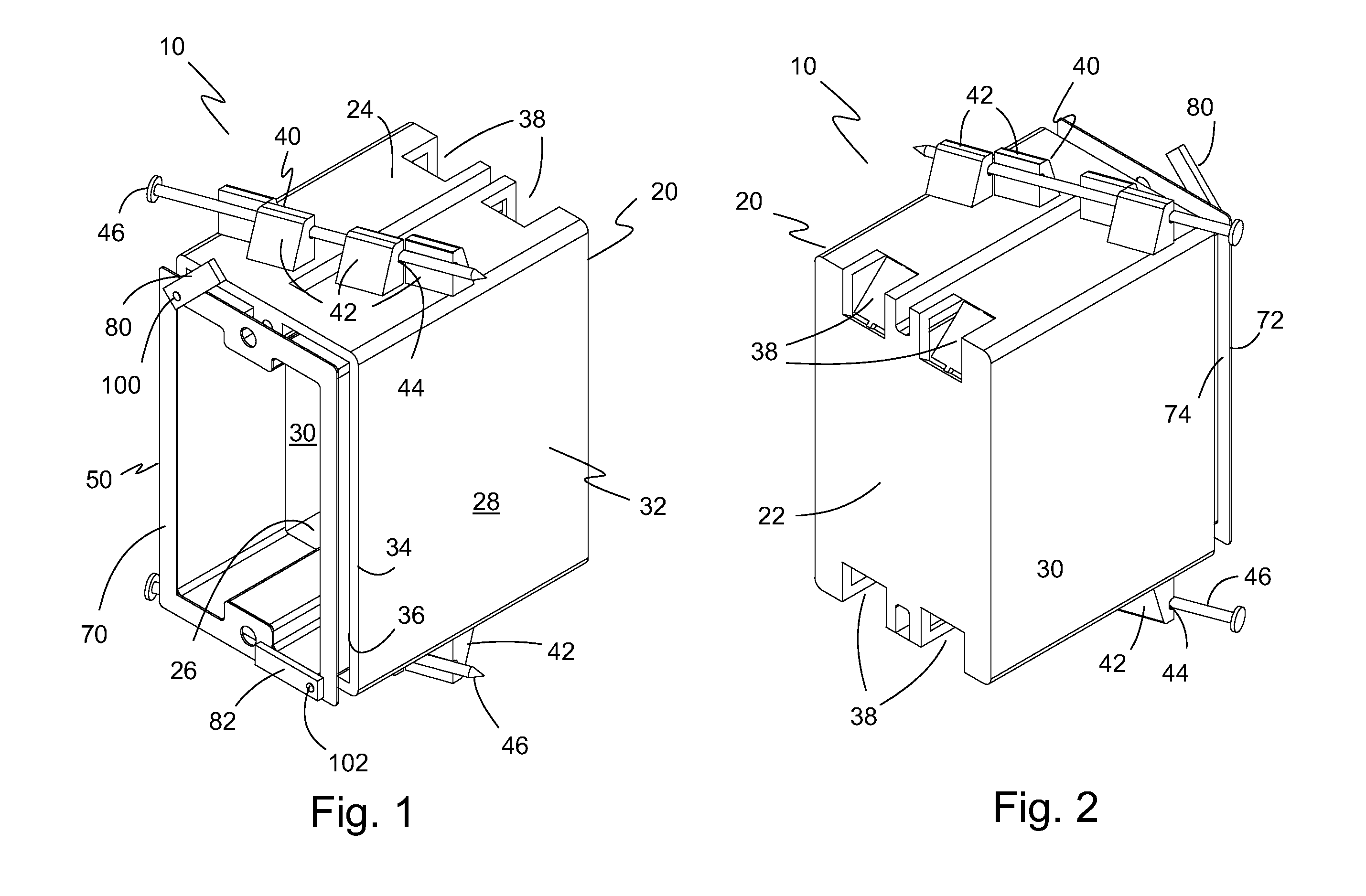
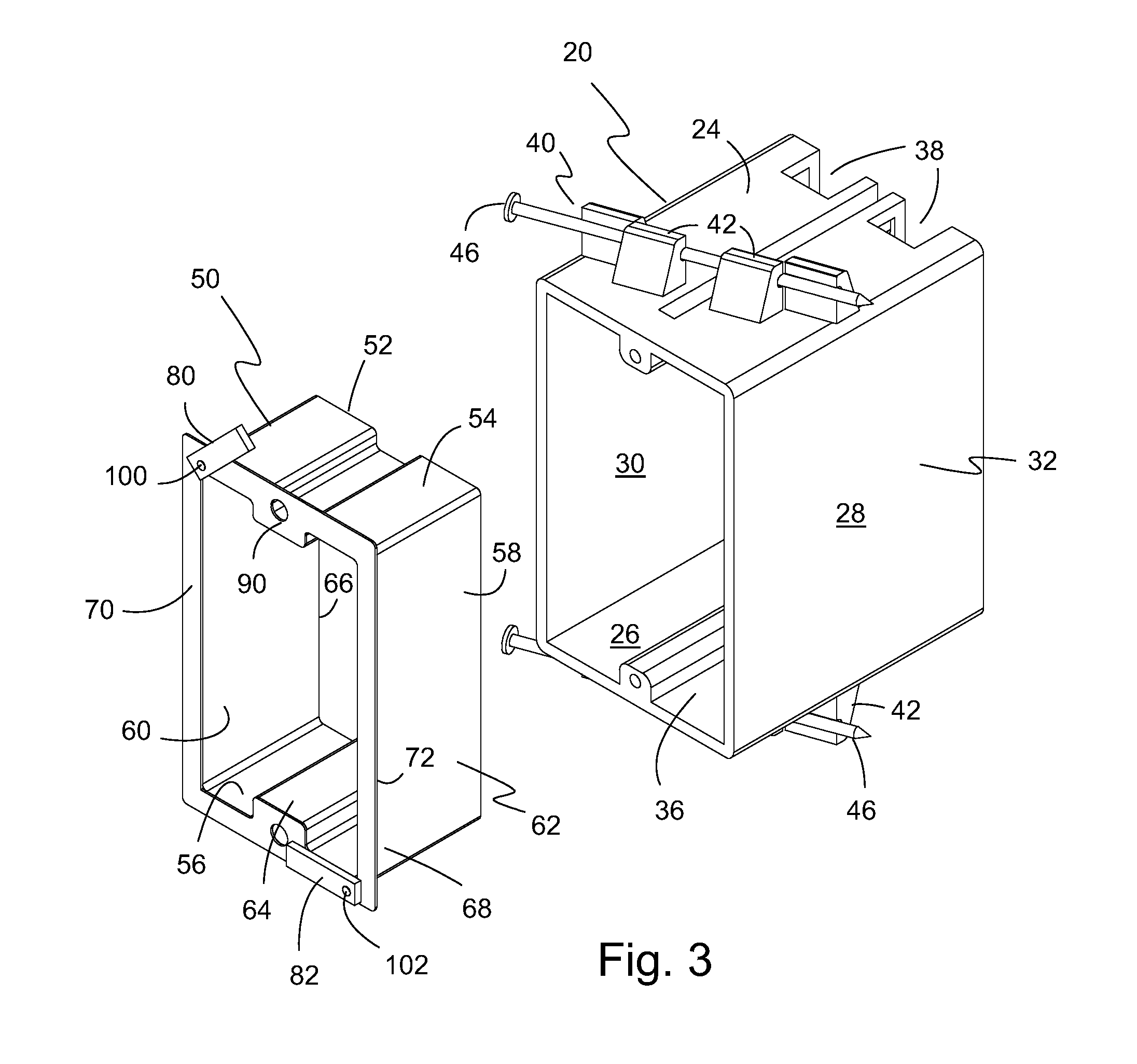
sealant that enters into the interior of the electrical box. In one embodiment of the present invention, there is provided an adjustable electrical box including a box element having an
enclosure with a box perimeter wall, a back wall and a front opening, a box extender having a tubular body telescopically received in the box opening, and a first stop member pivotally connected to the box extender. The tubular body has an extender perimeter wall, an open front, an open back, and a lateral outward
flange connected to a portion of the open front and extending a distance no greater than to the perimeter of the box element. The first stop member is pivotally connected to the lateral outward flange of the box extender where the first stop member pivots between a first non-engaging position and a second surface-engaging position.
[0027]In another embodiment of the present invention, the extender perimeter wall has a sliding fit to the box perimeter wall sufficiently close to allow the application of an insulating foam sealant between the box element and an edge of a wall covering opening that exposes the opening of the box element while minimizing penetration of the insulating foam sealant to the interior of the box element.
[0028]In a further embodiment of the present invention, the first opposed side and the second opposed side of the box extender has a sliding fit to the pair of opposed sidewalls of the box element sufficiently close to allow the application of an insulating foam sealant between the box element and an edge of a surface opening that exposes the opening of the box element while minimizing penetration of the insulating foam sealant to the interior of the box element.
[0031]In another embodiment, there is disclosed a method of efficiently extending an electrical box opening flush with a wall covering. The method includes providing an electrical box for new construction installation that includes a box element forming an
enclosure with a front opening, a box extender telescopically received in the box front opening, and a first stop member pivotally connected to a lateral outward flange of the box extender where the first stop member pivots between a first non-engaging position and a second surface-engaging position, attaching the electrical box to a
wall stud and installing
electrical wiring to the electrical box, applying a wall covering to the
wall stud and creating an opening for exposing the electrical box and
electrical wiring, sliding the box extender outwardly from the box until the lateral outward flange is beyond the wall surface, pivoting the first stop member from the first non-engaging position to the second surface-engaging position, sliding the box extender inwardly into the box until the first stop member engages the surface of the wall covering, and
coupling an electrical component to the
electrical wiring and to the electrical box.
[0032]In a further embodiment of the method, the method includes sealing the space between the electrical box and the edge of the opening in the wall covering with an insulating foam sealant minimizing air and thermal flow between the space behind the wall covering and the room where the sliding fit between the box extender and the box element is sufficiently close to minimize the penetration of insulating foam sealant into the box element.

