Solar cell sheet

Inactive Publication Date: 2012-09-13
SONY CORP
View PDF9 Cites 0 Cited by
  • Summary
  • Abstract
  • Description
  • Claims
  • Application Information

AI Technical Summary

Benefits of technology

[0009]In light of the foregoing, it is desirable to provide a new and improved solar cell sheet that offers excellent portability, and that further allows solar cell panels to be easily installed and stored.
[0023]According to the present invention described above, it is possible to provide a novel and improved solar cell sheet that offers excellent portability and that further allows solar cell panels to be easily installed and stored.

Problems solved by technology

As described above, as permanent installation is a prerequisite of known solar cell panels, they are not designed to be used while being moved.

Method used


Image

  • Solar cell sheet
  • Solar cell sheet
  • Solar cell sheet

Examples


first embodiment

1. FIRST EMBODIMENT

1-1. Structure of Photovoltaic Power Generating System

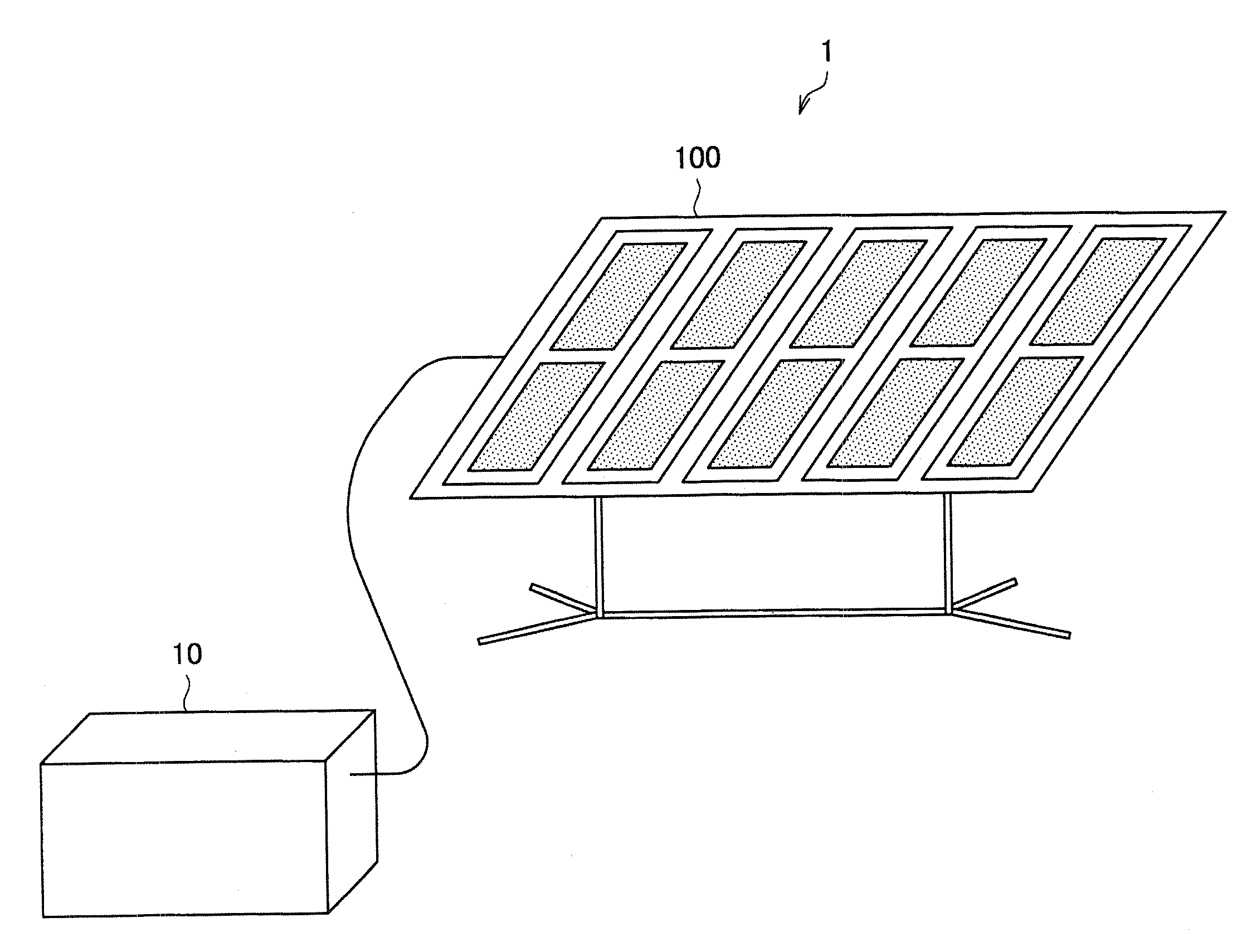
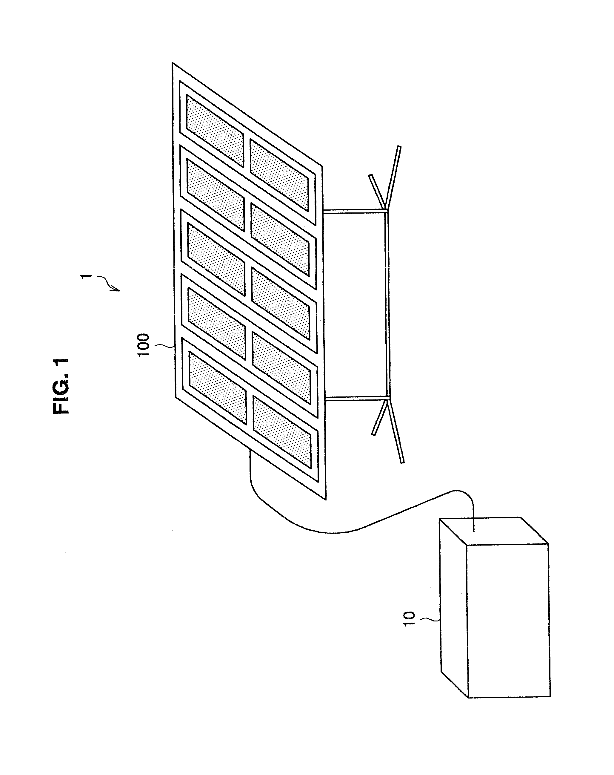
[0058]First, a structure of a photovoltaic power generating system 1 according to a first embodiment of the present invention will be explained. FIG. 1 is an explanatory diagram showing a structure of the photovoltaic power generating system 1 according to the first embodiment of the present invention. The photovoltaic power generating system 1 shown in FIG. 1 has a structure in which electric power, which is generated by receiving irradiation of sunlight on a light receiving surface of a solar cell panel, is stored in a battery. Hereinafter, the structure of the photovoltaic power generating system 1 according to the first embodiment of the present invention will be explained with reference to FIG. 1.

[0059]As shown in FIG. 1, the photovoltaic power generating system 1 according to the first embodiment of the present invention includes a solar cell sheet 100 that generates electric power by receiving irradiatio...

second embodiment

2. SECOND EMBODIMENT

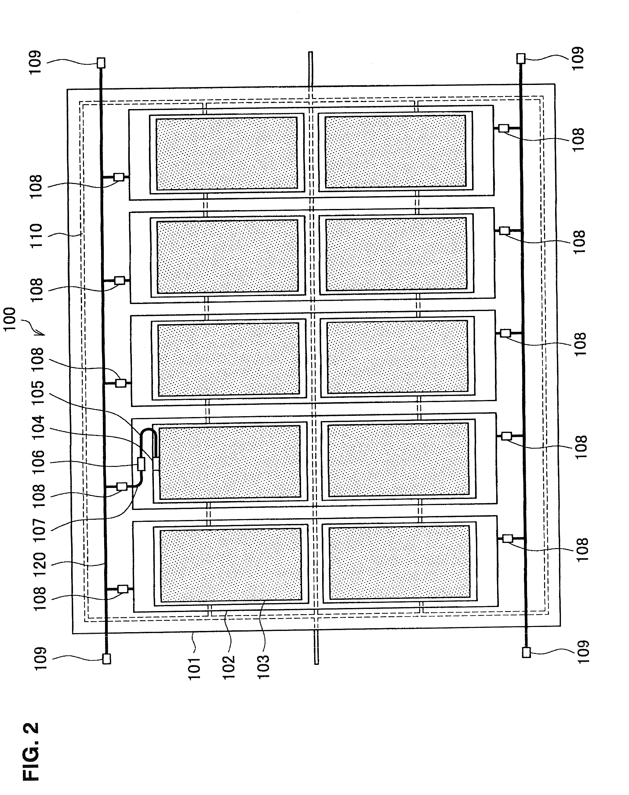
[0104]In the above-described first embodiment of the present invention, the solar cell sheet 100 is described in which the rectangular solar cell panels 103 are attached to the rectangular strip-shaped sheet 102 such that the lengthwise direction of the strip-shaped sheet 102 is aligned with the lengthwise direction of the solar cell panels 103.

[0105]The present invention is not limited to an example relating to attaching solar cell panels to a strip-shaped sheet. In a second embodiment of the present invention, a solar cell sheet will be described in which a rectangular strip-shaped sheet and similarly rectangular solar cell panels are attached such that the lengthwise direction of the strip-shaped sheet and the lengthwise direction of the solar cell panels are respectively perpendicular to each other.

[0106]FIG. 13 is an explanatory diagram showing a structure of a solar cell sheet 200 according to the second embodiment of the present invention. Hereinafter, the...

third embodiment

3. THIRD EMBODIMENT

[0125]In the above-described first embodiment of the present invention, in the explanation of the solar cell sheet 100, the solar cell panels 103 are attached to the strip-shaped sheet 102 such that the lengthwise direction of the strip-shaped sheet 102 is aligned with the lengthwise direction of the solar cell panels 103. Further, in the above-described second embodiment of the present invention, in the explanation of the solar cell sheet 200, the solar cell panels 203 are attached to the strip-shaped sheet 202 such that the lengthwise direction of the strip-shaped sheet 202 and the lengthwise direction of the solar cell panels 203 are respectively perpendicular to each other.

[0126]However, the attachment of the solar cell panels to the strip-shaped sheet is not limited to the above-described examples. For example, by attaching the solar cell panels to the strip-shaped sheets such that when attaching to the main sheet, the solar cell panels form a mesh which has ...


PUM


Abstract

There is provided a solar cell sheet including a solar cell panel that generates electric power by receiving irradiation of sunlight, a first sheet to which a number of the solar cell panels are attached such that a reverse surface of a light receiving surface of each of the solar cell panels is attached to the first sheet with a predetermined interval between each of the solar cell panels, the number of the solar cell panels being sufficient to obtain desired electric power, and a second sheet to which is removably attached to the at least one first sheet to which the solar cell panels are attached, the at least one first sheet being removably attached to the second sheet on a reverse surface to a surface on which the solar cell panels are attached.

Description

BACKGROUND OF THE INVENTION[0001]1. Field of the Invention[0002]The present invention relates to a solar cell sheet.[0003]2. Description of the Related Art[0004]It is conceivable that usage of solar cell panels, which generate electric power by receiving irradiation of sunlight, will become widespread as a measure against global warming, to reduce the amount of carbon dioxide emissions. A prerequisite of known solar cell panels is that a plurality of solar cells are used in combination on top of a roof, where it is easy to receive the irradiation of sunlight, and the panels are designed and manufactured for permanent installation. As a result, a weight of the panels is great, and it is not easy to move solar cell panels that have once been installed.[0005]With known solar cell panels, although there is some sense that the solar cell panels are used individually in order to receive a supply of electric power, there is a stronger sense that the solar cell panels are used to supplement...

Claims


Application Information

Patent Timeline
IPC IPC(8): H01L31/05
CPCH01L31/0504Y02E10/50H02S20/25H02S30/20Y02B10/12Y02B10/10
Inventor ISHIBASHI, YOSHIHITOTAJIMA, SHIGERUYOSHIMURA, TSUKASA
Owner SONY CORP
Why Eureka
Try Eureka