

Split Flywheel Assembly With Attitude Jitter Minimization
a flywheel and assembly technology, applied in the field of satellites, can solve the problems of reducing the amplitude of attitude jitter
Active Publication Date: 2012-09-20
UNIV OF FLORIDA RES FOUNDATION INC
View PDF17 Cites 15 Cited by
- Summary
- Abstract
- Description
- Claims
- Application Information
AI Technical Summary
Benefits of technology
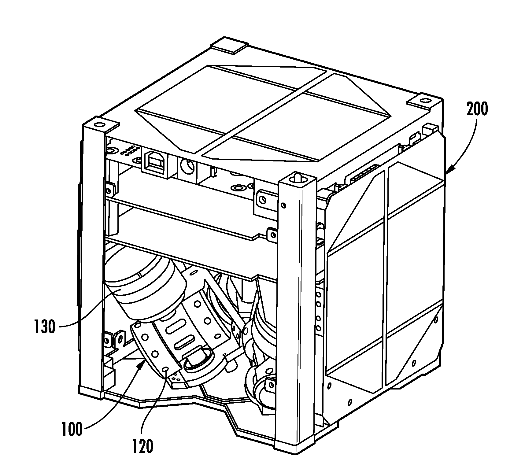
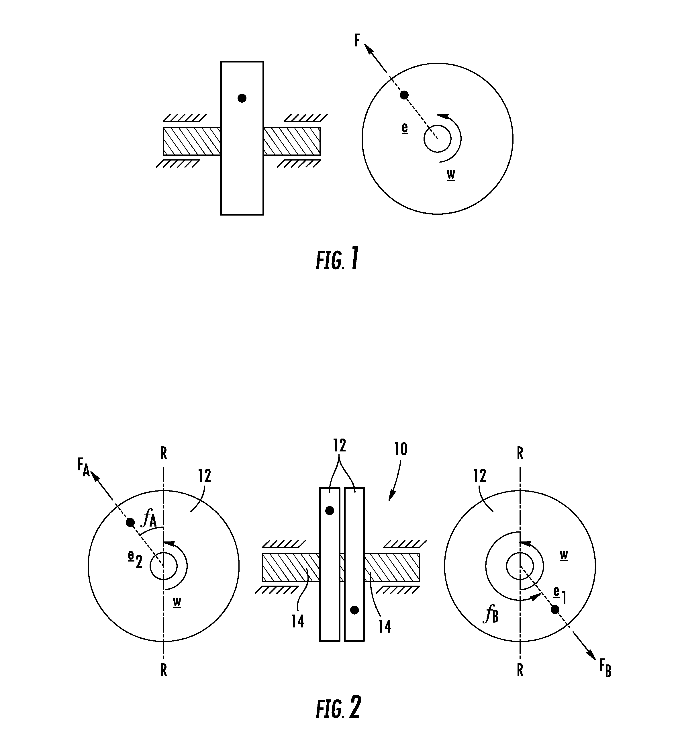
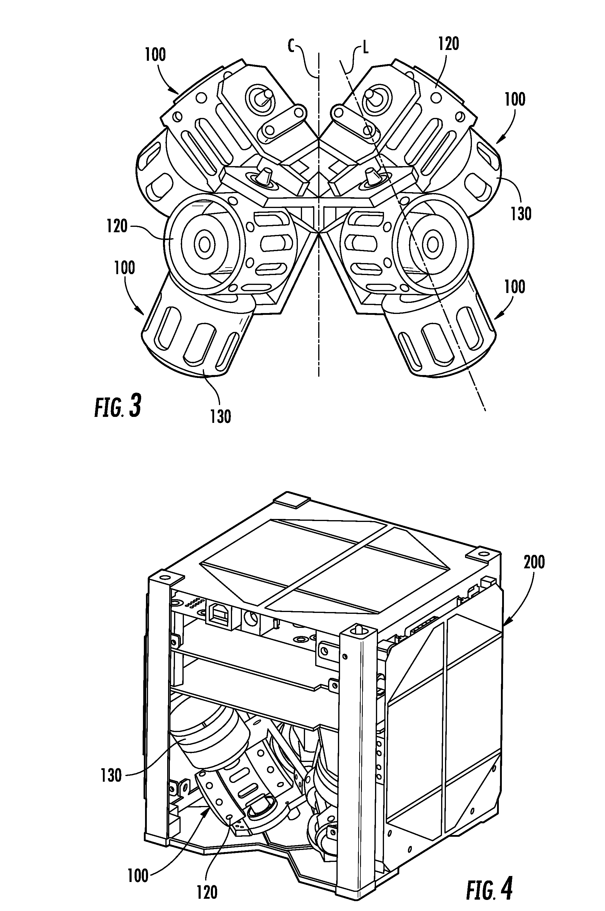
[0008]Various embodiments of the present invention include a split flywheel design that minimizes the amplitude of attitude jitter in satellites, and in some embodiments, adds redundancy. According to various embodiments, the split flywheel design allows manipulation of the phase difference between two or more flywheels spinning at substantially the same angular velocity to negate each other's imbalance (due to eccentricity in their centers of mass). In certain embodiments, the split flywheel design includes two or more separate flywheels in place of one flywheel, and the flywheels are mounted such that they are substantially concentric and axially (e.g., axially) aligned. In addition, in certain embodiments, the flywheel design includes a coupling apparatus adapted to selectively couple the flywheels together. In one particular embodiment, the flywheels are substantially geometrically identical and may be mounted substantially symmetrically on a central yoke. Each flywheel may be spun (or capable of being spun) using a separate motor at a desired speed.
[0009]In one embodiment, the flywheels are configured so that their overall mass and inertia is less than about 15% greater than the overall mass and inertia of a single flywheel assembly capable of being used in an identical satellite. According to one aspect, the mass and inertia of the flywheels are substantially equivalent (e.g., equivalent) to the mass and inertia of a single flywheel that may be used in a particular application. In addition, in one embodiment, the motors used are frameless, brushless DC motors, which may allow the use of a common housing for mounting the motor and the flywheel. This may save considerable amounts of mass and volume.
[0011]In one embodiment, a split flywheel assembly for minimizing the amplitude of attitude jitter is provided. The split flywheel assembly includes a plurality of independent concentric flywheels axially aligned and in operable engagement with one another such that each flywheel is configured to be independently controlled in order to manipulate the phase difference therebetween. For example, a pair of independent flywheels may be in operable engagement with one another. A clutch may be used to selectively engage and disengage the flywheels such that the flywheels are configured to spin concurrently or independently of one another in the engaged or disengaged positions, respectively, in order to obtain a desired phase difference. In one application, the assembly is configured to be mounted within a satellite such that the satellite can be rebalanced by independently controlling the speed of rotation of at least one of the flywheels to adjust the phase difference therebetween.
[0012]According to another embodiment, a method for minimizing the amplitude of attitude jitter is provided. In particular, the method includes providing a plurality of independent concentric flywheels axially aligned and in operable engagement with one another and independently controlling each flywheel so as to manipulate the phase difference therebetween. The controlling step may include selectively engaging and disengaging the flywheels such the flywheels are configured to spin concurrently or independently of one another in the engaged or disengaged positions, respectively. In one aspect, the controlling step includes independently controlling the speed of rotation of at least one of the flywheels to adjust the phase difference therebetween. Moreover, the controlling step may include incrementing and decrementing the speed of rotation of at least one of the flywheels (e.g., providing one or more trapezoidal velocity commands). The method may further include spinning the flywheels with respective motors at substantially the same speed at a desired phase difference. Furthermore, the method may include stopping rotation of one of the motors and spinning the flywheels concurrently with a single motor. According to one aspect, stopping rotation of one of the motors and spinning the flywheels concurrently occurs simultaneously.
Problems solved by technology
This may save considerable amounts of mass and volume.
However, when one of the flywheels is controlled to alter the phase difference between the flywheels to minimize jitter or imbalance, the clutch may be released to uncouple the flywheels.
Method used
View moreImage
Smart ImageViewing Examples

Examples
case 1
[0037]I__ccu=[1.7E-30001.7E-30001.7E-3]Kgm2I__OAA=I__OBB=[0.85E-60000.5E-60000.5E-6]Kgm2MA=MB=0.025KgmA=mB=0.001KgeA=eB=0.0001mr_A=[0.03500]Tmr_B=[0.0300]TmφB-φA=0ω_A=ω_B=523rad / s
case 2
[0038]The parameters are the same as in case 1 except eB=0.001 m
case 3
[0039]The parameters are the same as in case 1 except rA=[0.045 0 0]T m
Login to View More PUM
 Abstract
Various embodiments of the present invention include assemblies and methods for minimizing the amplitude of attitude jitter. In one embodiment, a split flywheel assembly includes a plurality of independent concentric flywheels axially aligned and in operable engagement with one another such that each flywheel is configured to be independently controlled in order to manipulate the phase difference therebetween.
Description
FIELD OF THE INVENTION[0001]Embodiments of the present invention relate to satellites and, more particularly, to a flywheel assembly for minimizing the amplitude of attitude jitter in satellites.BACKGROUND[0002]Small satellites are evolving rapidly to augment the functions of larger satellites as well as individually perform some of the tasks such as stereo-imaging and directional communication which were earlier possible only by their larger counterparts. This evolution is gaining ground as attitude control actuators are being developed for smaller classes of satellites. Actuators based on the principle of momentum exchange like reaction wheels, momentum wheels and control moment gyroscopes (CMGs) have multiple spinning wheels or flywheels. The CMG is one such actuator that enables rapid retargeting and precision pointing which are necessary for applications mentioned above. The CMG has flywheels mounted on gimbals which when actuated produces gyroscopic torque that is the control ...
Claims
Login to View More Application Information
Patent Timeline
 Patent Type & AuthorityApplications(United States)
IPC IPC(8): B64G1/28
CPCB64G1/28G05D1/0808F16F15/30
InventorNAGABHUSHAN, VIVEKFITZ-COY, NORMAN G.
OwnerUNIV OF FLORIDA RES FOUNDATION INC