
High resolution and high precision vector magnetometer

a vector magnetometer, high-precision technology, applied in the field of vector magnetometers, can solve the problems of resolution and precision much lower than the intrinsic performance of the scalar magnetometer, resolution and precision, and detrimental to the linearity of the sensor

Active Publication Date: 2014-07-08
COMMISSARIAT A LENERGIE ATOMIQUE ET AUX ENERGIES ALTERNATIVES
View PDF8 Cites 7 Cited by
  • Summary
  • Abstract
  • Description
  • Claims
  • Application Information

AI Technical Summary

Benefits of technology

The patent describes a way to reduce the magnetic interference between two objects that have conductive windings. The solution involves swiveling the object with the windings in it so that it is perpendicular to the direction of the magnetic field. This reduces the likelihood of interference between the magnetic fields and improves the performance of the device.

Problems solved by technology

The vector magnetometer illustrated in FIG. 1 gives good results, however has performances in resolution and precision much lower than the intrinsic performances of the scalar magnetometer it uses.
The precision error has an accuracy component and a reliability component.
These restrictions in resolution and precision are essentially due to the fact that the modulation amplitudes of the magnetic field along the axes Ox, Oy, Oz, hereinafter called vector modulation amplitudes, cannot be selected too high, otherwise this would be detrimental to the sensor linearity and would introduce measurement distortion.

Method used


Image

  • High resolution and high precision vector magnetometer
  • High resolution and high precision vector magnetometer
  • High resolution and high precision vector magnetometer

Examples


Embodiment Construction

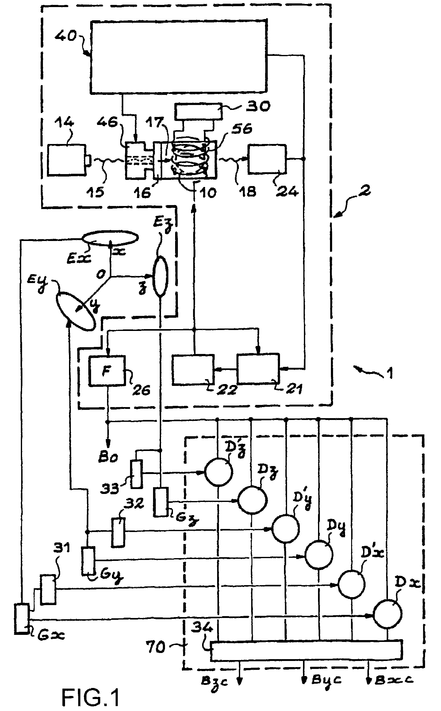
[0020]The present invention is defined by a device for measuring the components of an ambient magnetic field including:[0021]an optically pumped scalar magnetometer comprising a cell filled with a gas, a laser source emitting a light beam, a polarizer rectilinearly polarizing said beam along a direction of polarization, a photodetector receiving the polarized beam that passed through the cell and providing an electrical signal, a coil surrounding the cell, powered by a radiofrequency generator and the axis of which registers with said direction of polarization, frequency locking means receiving said electrical signal and locking the frequency of the radiofrequency generator to the Larmor frequency, a frequency estimator estimating the frequency of the radiofrequency signal generated by said generator, the scalar magnetometer providing a signal representative of the module of the magnetic field in which the cell is located from the frequency thus estimated;[0022]two conductive windin...


PUM


Abstract

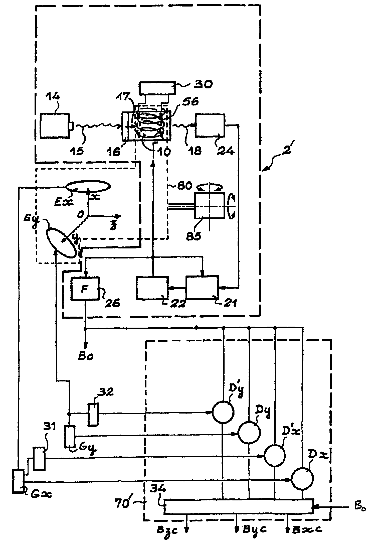
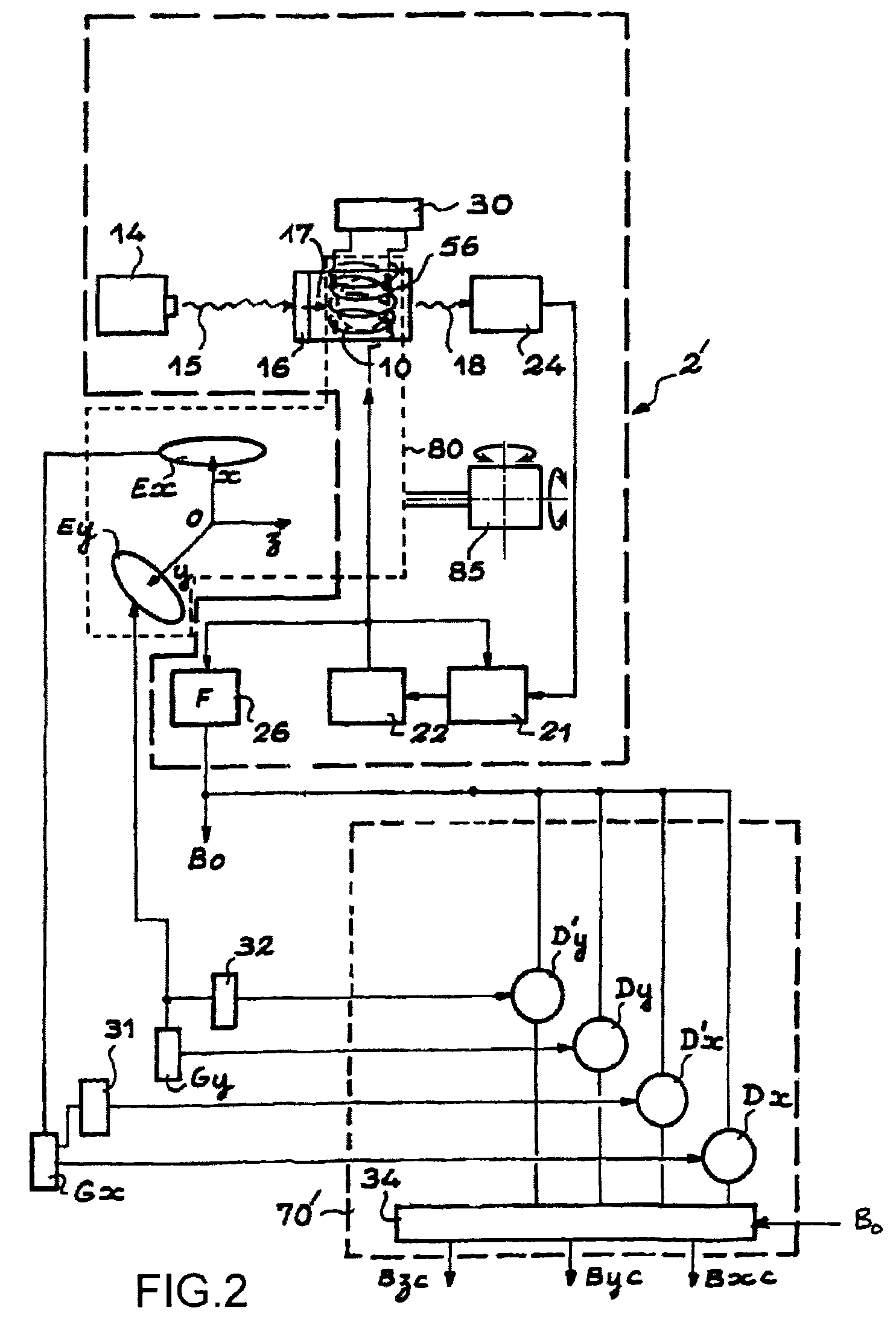
The present invention relates to a vector magnetometer for measuring the components of an ambient magnetic field. This vector magnetometer comprises an optically pumped scalar magnetometer (2′), a pair of conductive windings (Ex,Ey) having distinct axes (Ox, Oy) and powered by two generators (Gx, Gy) having distinct frequencies. The RF coil (56) of the scalar magnetometer and the conductive windings (Ex,Ex) are mechanically integral with a swivel support (85) mounted on swivel means. The axis of the RF coil is in the same plane as the axes Ox, Oy. The support is swivelled so that this plane is substantially orthogonal to the ambient magnetic field.

Description

TECHNICAL FIELD[0001]The present invention relates to the field of vector magnetometers and more particularly to those that are optically pumped.STATE OF PRIOR ART[0002]Optically pumped scalar magnetometers have been known for several decades. They are based on the magnetic resonance between Zeeman lines, which is amplified using optical pumping. For example, in a magnetometer of this type using a helium cell (4He), the helium atoms at the 11S0 level are excited at the 23S1 metastable level by means of the HF discharge. This 23S1 metastable level is divided in a Zeeman triplet in the presence of a static magnetic field. Atoms of the 23S1 level are optically pumped to the 23P0 level using a tunable laser. As a result, there is a different depletion of the different lines of the triplet, by selective excitation at the 23P0 level. The atoms thus excited come back through spontaneous emission to the 23S1 metastable level. A magnetic resonance is induced between the triplet levels by mea...

Claims


Application Information

Patent Timeline
Patent Type & Authority Patents(United States)
IPC IPC(8): G01R33/02G01R33/028G01R33/24G01R33/26G01R33/44G01V3/00
CPCG01R33/24G01R33/028G01R33/26G01R33/44
Inventor JAGER, THOMASLEGER, JEAN-MICHEL
Owner COMMISSARIAT A LENERGIE ATOMIQUE ET AUX ENERGIES ALTERNATIVES
Learn More