Hollow cylindrical thermal shield for a tubular cryogenically cooled superconducting magnet

a superconducting magnet and cylindrical technology, applied in the direction of superconducting magnets/coils, magnetic bodies, container discharge methods, etc., can solve the problems of secondary and tertiary eddy currents, mechanical vibration of the ovc and the thermal radiation shield is heated. the effect of reducing the magnitude of resonance, minimizing the amplitude of mechanical vibration, and reducing the problem of inner tube mechanical resonan

Active Publication Date: 2012-11-27
SIEMENS HEALTHCARE LTD
View PDF8 Cites 11 Cited by
  • Summary
  • Abstract
  • Description
  • Claims
  • Application Information

AI Technical Summary

Benefits of technology

[0016]Problematic peaks in GCIH occur when the gradient coils are pulsed at frequencies close to the resonant frequencies of both the inner tubes of the thermal radiation shield and the OVC. Problematic mechanical resonance of the inner tubes may be reduced by separation of the resonant frequencies of inner tube of the OVC and the inner tube of the thermal radiation shield. Furthermore, the magnitude of resonance may be reduced by substantial stiffening of the shield bore tube thereby to minimize the amplitude of mechanical vibration, and so reduce the magnitude of any secondary or tertiary eddy currents and heating induced in the thermal radiation shield, the cryogen vessel or other cryogenically cooled components.
[0017]The present invention accordingly provides a structure having a stiffer (more mechanically rigid) inner tube of the thermal radiation shield. The inner tube of the thermal radiation tube may be effectively made heavier, yet without increasing the required coil diameter. There need be no increase in wire cost, or reduction in bore diameter of the thermal radiation shield.
[0018]The stiffened inner tube of the thermal radiation shield provides substantial separation of resonant frequencies of the inner tubes of the OVC and the thermal radiation shield. The amplitude of mechanical vibration due to gradient coil pulsing is reduced, leading in turn to reduced eddy currents in the cold mass.
[0019]The present invention includes a hollow cylindrical thermal radiation shield having an inner cylindrical tube, and a cylindrical stiffener, extending axially at least part of the axial length of the inner cylindrical tube. The stiffener is of greater diameter than the inner cylindrical tube, and is joined at intervals to the inner cylindrical tube, thereby to improve the mechanical rigidity of the inner cylindrical tube.
[0020]Preferably, the inner cylindrical tube of the thermal radiation shield is thinner than in a conventional arrangement, allowing coil diameters to be reduced, saving wire cost; or the bore diameter of the OVC may be increased.
[0021]According to an aspect of the invention, the cylindrical stiffener is able to react much of the force on the inner tube and end pieces of the thermal radiation shield, enabling the inner tube itself to be of thinner material than is conventional. This in turn may permit a reduction in the diameter of the magnet coils, and a corresponding reduction in wire cost; or the bore diameter of the OVC may be increased. Furthermore, the inner tube and end pieces of the thermal radiation shield may be constructed of high purity aluminum.

Problems solved by technology

Such eddy currents cause heating of the thermal radiation shield.
However, secondary and tertiary eddy currents remain a problem.
Although the cryogen vessel is not subjected to the high-frequency varying magnetic fields of the gradient coils, the magnetic pulsing of the gradient coils causes mechanical vibration of the OVC and the thermal radiation shields.
These vibrations, within the magnetic field of the coils, cause induced eddy currents in the material of the OVC and the thermal radiation shields.
However, an increased boil-off of cryogen will occur due to GCIH of the cryogen vessel and the coils and radiant heating caused by GCIH of the thermal radiation shield.
As a result, there is a risk that the coils 10 will heat, and quench, even in response to a relatively small amount of heating.
This does not prevent or reduce the magnitude of eddy currents in the cryogen vessel, but reduces the resultant heating due to the reduced electrical resistance of the cryogen vessel.
This approach has been found to have limited success, as the reduced resistance of the cryogen vessel has been found to lead to increased eddy currents.
This results in an increase in the diameter of the coils, and a great increase in wire cost, in order to keep the bore of the OVC at the required diameter.

Method used


Image

  • Hollow cylindrical thermal shield for a tubular cryogenically cooled superconducting magnet
  • Hollow cylindrical thermal shield for a tubular cryogenically cooled superconducting magnet
  • Hollow cylindrical thermal shield for a tubular cryogenically cooled superconducting magnet

Examples


Embodiment Construction

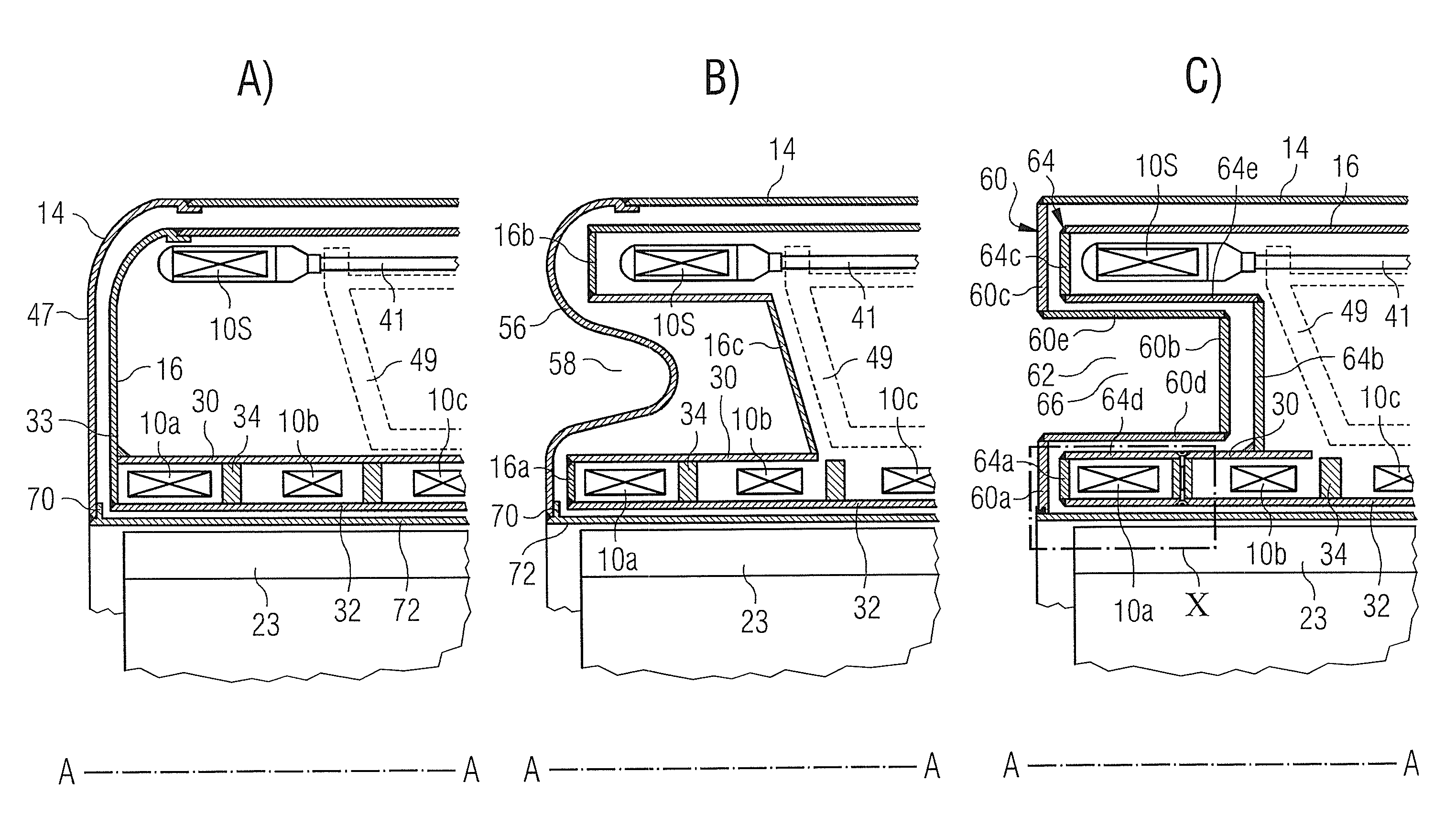
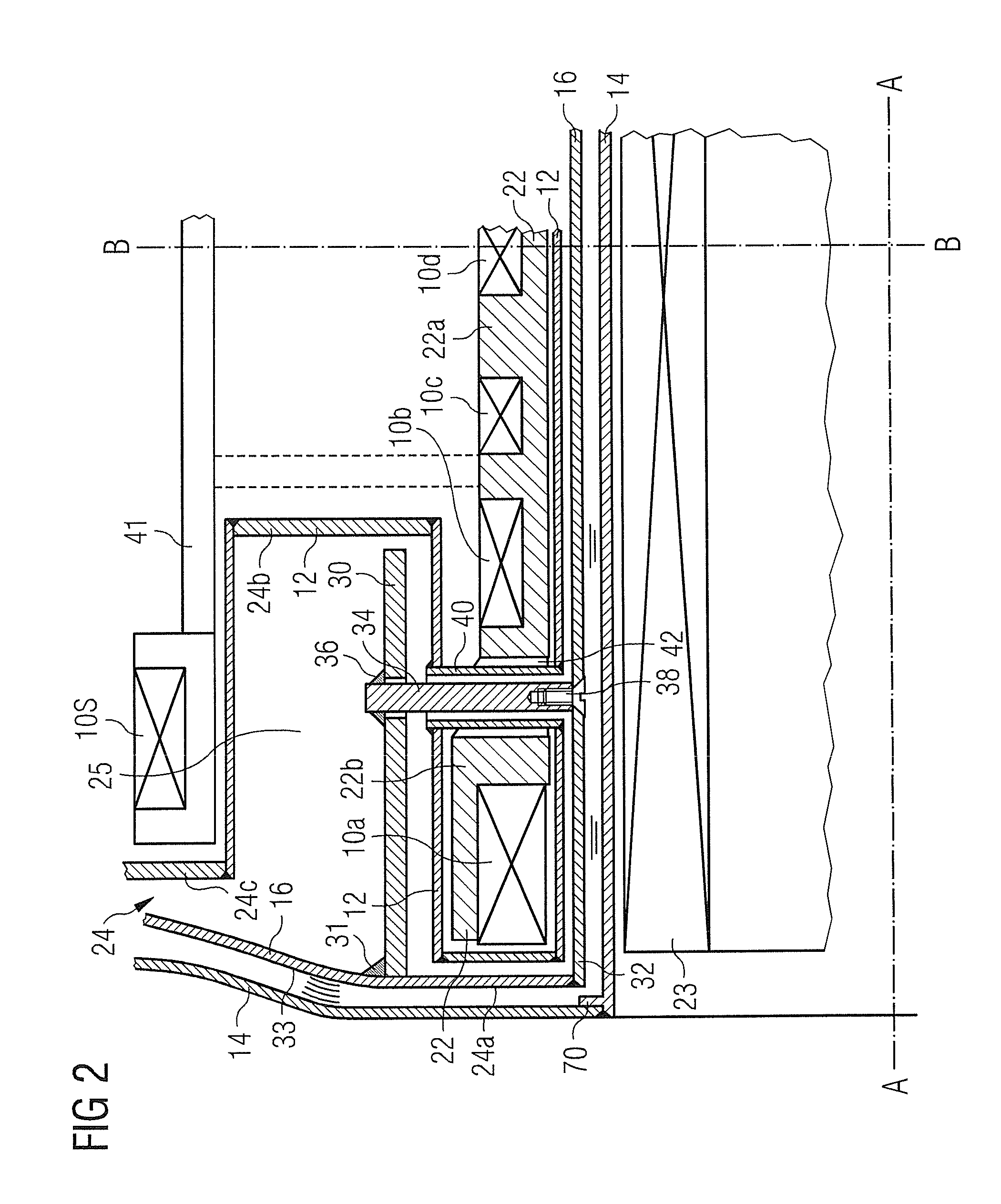
[0035]FIG. 2 shows an embodiment of the present invention, as applied to a “wet” magnet. Features corresponding to features of FIG. 1 are identified by corresponding reference numerals. FIG. 2 represents a part-axial cross section. The cross-section essentially has reflectional symmetry about axial centre line B-B and the magnet system is essentially symmetrical about axis A-A.

[0036]In the illustrated arrangement, coils 10a, 10b, 10c, 10d are mounted on a former 22. As is well-known in the art, the former may be made up of three parts: a central part 22a carrying central coils 10b, 10c, 10d, and two end-parts 22b each carrying an end coil 10a.

[0037]Active shield coils 10s, well known in themselves, are arranged on a separate mechanical support 41 at a greater radius about axis A-A than the central coils 10b, 10c, 10d. A cryogen vessel 12 surrounds the coils and former, and retains a liquid cryogen.

[0038]According to a feature of this embodiment of the invention, the annular end pie...


PUM

PropertyMeasurementUnit
thickaaaaaaaaaa
frequencyaaaaaaaaaa
superconductingaaaaaaaaaa

Abstract

A hollow cylindrical thermal shield for a tubular cryogenically cooled superconducting magnet, has a first axis, an inner cylindrical tube having an axis aligned with the first axis, an outer cylindrical tube of greater diameter than the diameter of the inner cylindrical tube, having an axis aligned with the first axis, and annular end pieces, joining the inner cylindrical tube and the outer cylindrical tube to form an enclosure. The hollow cylindrical thermal shield further has a cylindrical stiffener, extending axially at least part of the axial length of the inner cylindrical tube, the stiffener being joined at intervals to the inner cylindrical tube, thereby to improve the mechanical rigidity of the inner cylindrical tube.

Description

BACKGROUND OF THE INVENTION[0001]1. Field of the Invention[0002]The present invention relates to a hollow cylindrical thermal shield for a tubular cryogenically cooled superconducting magnet, and particularly to such a thermal shield which is useful in MRI (Magnetic Resonance Imaging) systems due to reduction in gradient coil induced heating (GCIH) of cryogenically cooled apparatus.[0003]2. Description of the Prior Art[0004]Superconducting magnets for use in MRI systems are commonly cylindrical in shape, and the present invention is directed to such magnets. In an MRI system, a gradient coil assembly provides pulsed magnetic fields to provide the required spatial encoding of the imaging volume. Such time-variant magnetic fields will induce heating into conductive materials in the vicinity.[0005]FIG. 1 illustrates a typical arrangement of an MRI magnet system. Coils 10 are wound onto a former (not shown) which is placed within a cryogen vessel 12. The cryogen vessel is partially fill...

Claims


Application Information

Patent Timeline
Patent Type & Authority Patents(United States)
IPC IPC(8): H01F6/00F25B19/00G01V3/00
CPCH01F6/04G01R33/3804F17C13/007G01R33/3815G01R33/421H01F6/06
Inventor CALVERT, SIMON JAMES
Owner SIEMENS HEALTHCARE LTD
Why Eureka
Try Eureka