Compressor

a compressor and compressor technology, applied in the field of compressors, can solve the problems of clutch units, deterioration of the rotation shaft support function of the bearing, and high pressure of the refrigerant that cannot be released to the outside and applied pressure, etc., and achieve the effects of preventing lubricant from leaking, simple configuration, and stable maintenan

Inactive Publication Date: 2012-10-04
KEIHIN CORP
View PDF2 Cites 4 Cited by
  • Summary
  • Abstract
  • Description
  • Claims
  • Application Information

AI Technical Summary

Benefits of technology

[0018]In the compressor having the bearing which rotatably supports the rotation shaft, there are provided, between the outer ring and the inner ring of the bearing, the first seal member which is always in non-contact with the inner ring and which is provided on the side of the sealing member, and the second seal member which comes into contact with the inner ring and which is provided on the side of the clutch unit. Therefore, even when a refrigerant in a space in the boss portion located between the bearing and the sealing member is heated and expanded by rotation of the rotation shaft and pressure of the refrigerant becomes high, the refrigerant flows inside through a space between an inner edge of the first seal member and the inner ring, the refrigerant presses the second seal member toward the outside of the housing, the contacted state between the second seal member and the inner ring is released and the refrigerant is discharged outside of the housing through the gap. As a result, it is possible to avoid a case where excessive pressure is applied to the first and second seal members, and these seal members fall out from the inner ring and the outer ring, it is possible to reliably prevent lubricant from leaking from the bearing by the first and second seal members, and lubricating performance of the bearing by the lubricant can stably be maintained inexpensively with a simple configuration.

Problems solved by technology

However, a tiny amount of refrigerant in the housing enters the space through the oil seal, a temperature in the space rises due to the rotation of the rotation shaft, and if the refrigerant which entered the space expands with the temperature rise and a pressure therein rises, a high pressure of the refrigerant cannot be released to the outside and the pressure is applied to the seal member of the bearing.
When the seal member falls out, the sealing property in the bearing cannot be maintained, there is a possibility that moisture and dust enter the bearing from outside, the rotation shaft-supporting function of the bearing is deteriorated, a lubricant in the bearing leaks to the outside, the lubricant attaches to a clutch unit which controls transmission of a driving force from the internal combustion engine to the compressor, and the clutch unit slips.
This increases the number of producing steps and producing cost.

Method used


Image

  • Compressor
  • Compressor
  • Compressor

Examples


Embodiment Construction

[0023]A compressor of the present invention will be described in detail with reference to the accompanying drawings based on a preferred embodiment.

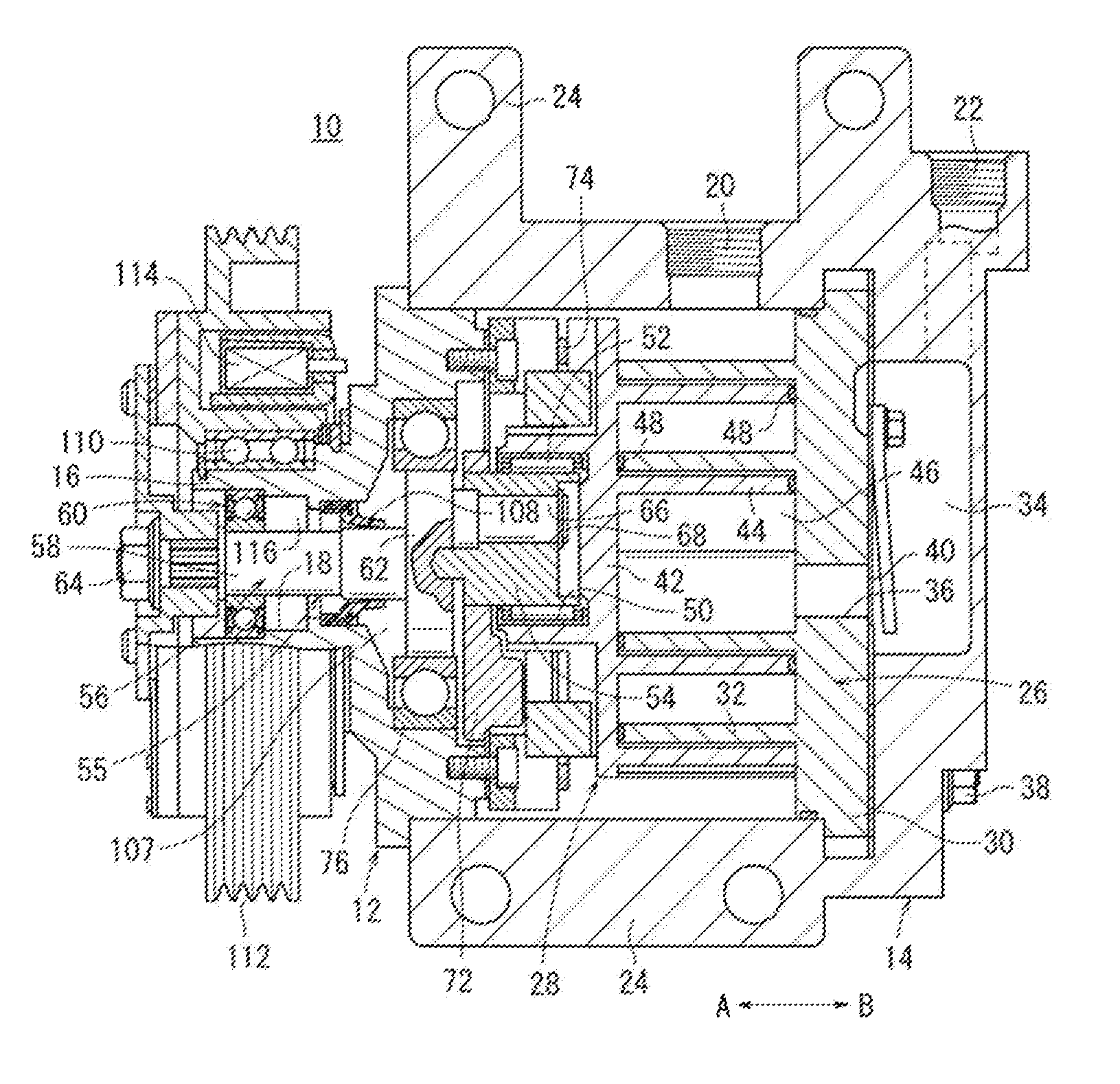
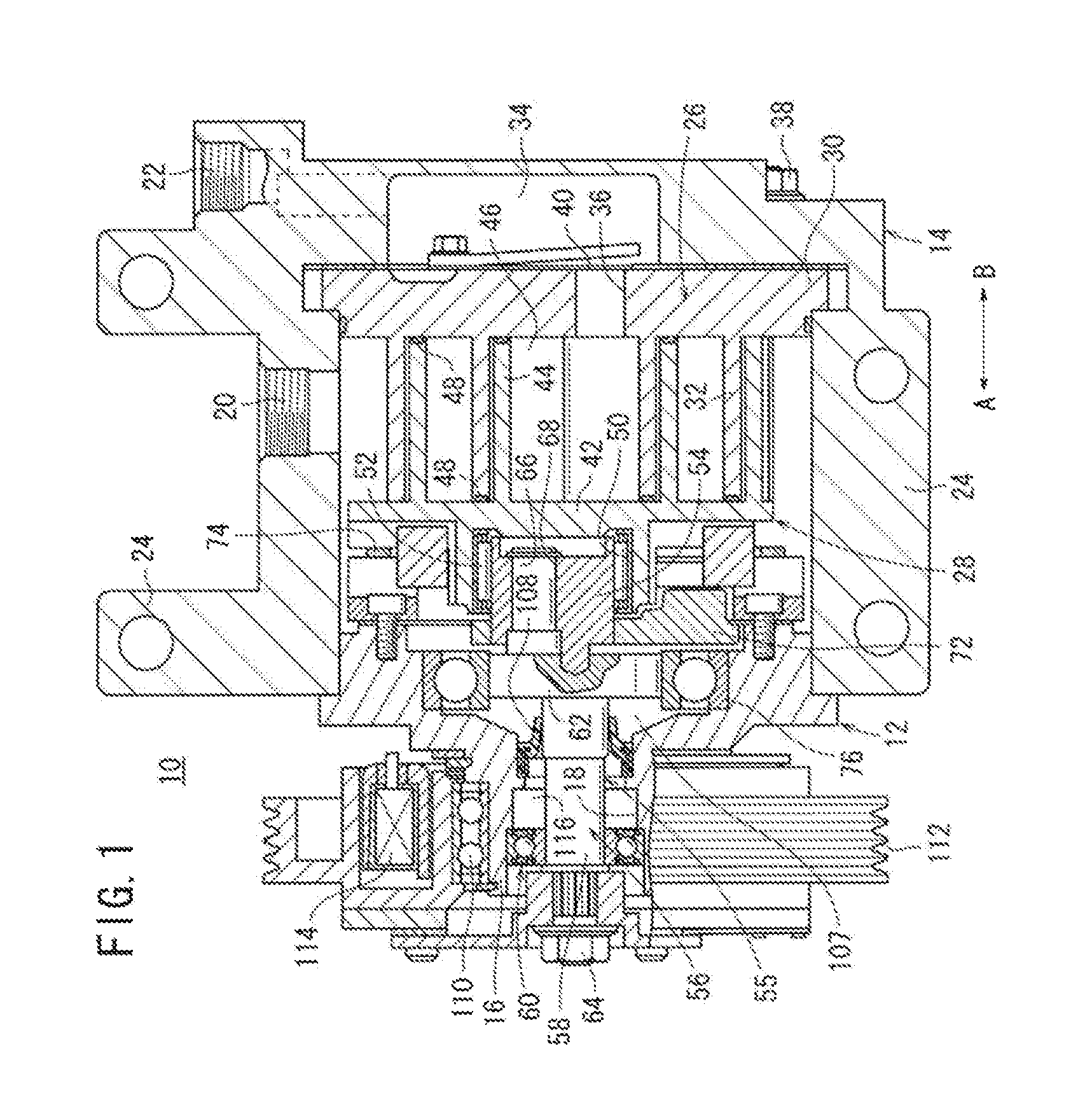
[0024]In FIG. 1, a reference symbol 10 represents a scroll compressor which is one example of a compressor according to an embodiment.

[0025]As shown in FIG. 1, this scroll compressor 10 includes a lid-shaped front housing (housing) 12 and a cup-shaped rear housing 14. The front housing 12 includes a boss portion 16 which projects toward one end of the front housing 12. A shaft hole 18 is formed in the boss portion 16 such that the shaft hole 18 penetrates the boss portion 16 along an axial direction (directions of arrows A and B) thereof. A shaft portion 58 of a later-described rotation shaft 56 is inserted into the shaft hole 18.

[0026]A suction port 20 is formed in an upper portion of the rear housing 14, and refrigerant gas is introduced into the rear housing 14 through the suction port 20. The suction port 20 opens at an outer periphe...


PUM


Abstract

A front housing configuring a scroll compressor is provided in its shaft hole with a first bearing, and the front housing rotatably supports a rotation shaft. The first bearing includes a ball bearing having a plurality of balls. First and second seal rings and are provided between an outer ring fixed to the front housing and an inner ring which abuts against an outer peripheral surface of the rotation shaft. A first seal ring disposed on the side of one side surface of the outer ring is provided such that the first seal ring is in non-contact with the inner ring, and the second seal ring disposed on the side of the other side surface of the outer ring abuts against the inner ring.

Description

TECHNICAL FIELD[0001]The present invention relates to a compressor used for a vehicular air conditioner for compressing a refrigerant therein by a driving force.[0002]The present application claims priority to Japanese Patent Application No. 2011-075187 filed in Japan on Mar. 30, 2011, and contents thereof are incorporated herein.BACKGROUND OF THE INVENTION[0003]A conventional compressor which compresses fluid such as a refrigerant includes a fixed scroll having a scroll fixed wall in a housing, a movable scroll disposed such that a scroll movable wall is engaged with the fixed wall, and a rotation shaft to which a rotation force is given utilizing a driving force of an internal combustion engine. A crankpin of the rotation shaft which is eccentric in its radial direction is engaged with the movable scroll, the rotation force of the rotation shaft is transmitted to the movable scroll through the crankpin, thereby turning the movable scroll, and fluid is compressed in a compression c...

Claims


Application Information

Patent Timeline
Patent Type & Authority Applications(United States)
IPC IPC(8): F04D29/08
CPCF04C18/0215F04C2240/50F04C27/009F16C2360/42
Inventor NISHIMURA, YUSUKEHIGUCHI, KAZUAKIMURAOKA, SATSUKIKUWATA, HIROKI
Owner KEIHIN CORP
Why Eureka
Try Eureka