Image display device

a display device and image technology, applied in the field of color display, can solve the problems of insufficient luminance of images and inability to accurately carry out color display, and achieve the effect of preventing insufficiency of luminance and accurate color display

Inactive Publication Date: 2012-11-22
SHARP KK
View PDF1 Cites 10 Cited by
  • Summary
  • Abstract
  • Description
  • Claims
  • Application Information

AI Technical Summary

Benefits of technology

[0029]The present invention provides an image display device including: display means having a display region, the display region being constituted by a plurality of pixels each having light transparency; and a backlight constituted by a plurality of light sources for backlighting the display region of the display means with light of different colors, said image display device displaying a color image by controlling, in accordance with an inputted video signal, an aperture ratio indicative of transmittance, of the plurality of pixels in the display means, for the light emitted from the plurality of light sources of the backlight, said image display device further including: a subframe generation section for dividing one frame of the video signal into a first subframe during which at least a light source of a first color emits light, a second subframe during which at least a light source of a second color emits light, and a third subframe during which a light source of a third color emits light, the subframe generation section including a first aperture ratio correction section for correcting, on the basis of a video signal of the first color included in the first subframe, a first aperture ratio corresponding to a pixel of the first color, a second aperture ratio correction section for correcting, on the basis of a video signal of the second color included in the second subframe, a second aperture ratio corresponding to a pixel of the second color, and a third aperture ratio correction section for correcting, on the basis of a video signal of the third color included in the third subframe, a third aperture ratio corresponding to a pixel of the third color, and the subframe generation section finding a difference between (i) a signal to be displayed, which signal is obtained from the first aperture ratio corrected by the first aperture ratio correction section in the first subframe and luminance distribution of a light source corresponding to a video signal of the second color included in the first subframe and (ii) the video signal of the second color included in the first subframe, and correcting, according to the difference found in the first subframe, the second aperture ratio corrected by the second aperture ratio correction section in the second subframe. This prevents insufficiency of luminance, and thus makes it possible to achieve an image display device capable of accurate color display.

Problems solved by technology

However, the method disclosed in Patent Literature 2 has the following problem.
Therefore, although the area active control can reduce occurrence of CB, some images may be insufficient in luminance if correction is carried out simply in consideration of luminance distribution of the LED for faithful reproduction of an original image.
That is, a color display cannot be carried out accurately.

Method used


Image

  • Image display device
  • Image display device
  • Image display device

Examples


Embodiment Construction

[0039]The following description discusses embodiments of the present invention in detail.

[0040]

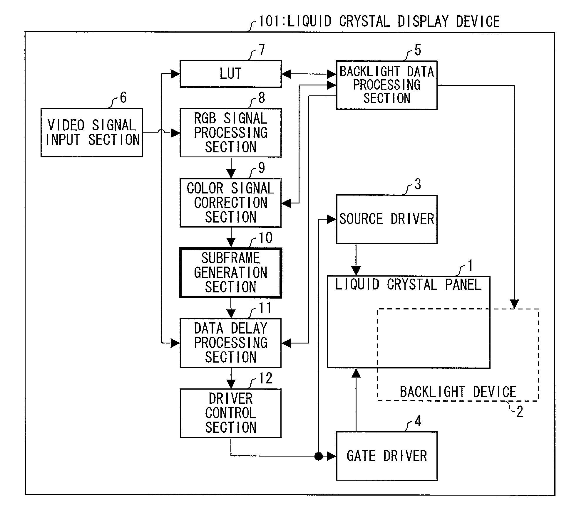
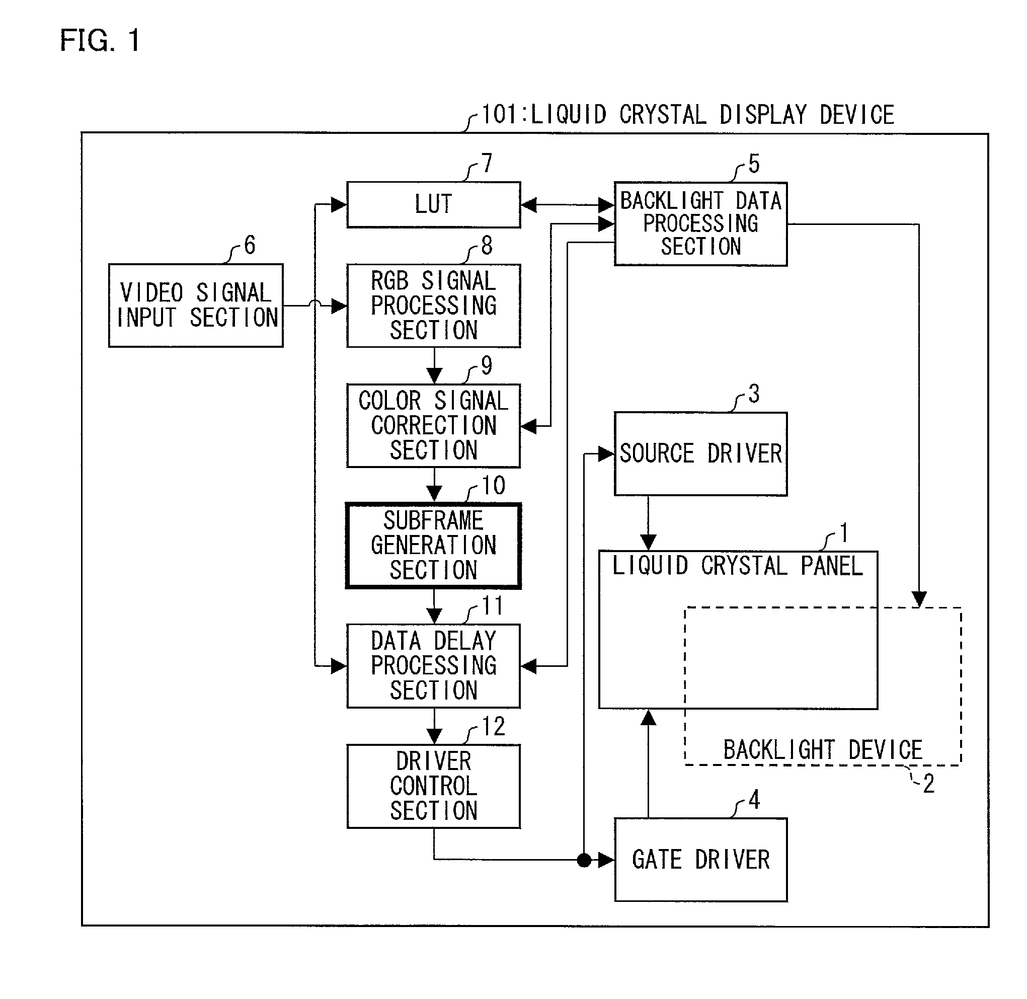
[0041]FIG. 1 is a block diagram schematically illustrating a liquid crystal display device, to which an image display device of the present invention is applied.

[0042]As illustrated in FIG. 1, a liquid crystal display device 101 includes: a liquid crystal panel (display means) 1 having a display region which is constituted by a plurality of pixels each having light transparency; a backlight device 2 constituted by a plurality of light sources for backlighting the display region of the liquid crystal panel 1 with light of different colors; a source driver 3; a gate driver 4; a backlight data processing section 5; a video signal input section 6; a LUT 7 (lookup table); an RGB signal processing section 8; a color signal correction section 9; a subframe generation section 10; a data delay processing section 11; and a driver control section 12.

[0043]The liquid crystal display device 101 is conf...


PUM


Abstract

An image display device of the present invention includes a subframe generation section (10) for dividing one frame of a video signal into a first subframe during which at least a green (G) light source emits light, a second subframe during which at least a red (R) light source emits light, and a third subframe during which a blue (B) light source emits light. The subframe generation section (10) finds a difference between (i) a signal to be displayed, which signal is obtained from an aperture ratio corrected in the first subframe and luminance distribution of a light source corresponding to a red (R) video signal included in the first subframe and (ii) the red (R) video signal included in the first subframe, and corrects, according to the difference found in the first subframe, an aperture ratio corrected in the second subframe. This prevents insufficiency of luminance, and thus makes it possible to carry out an accurate color display.

Description

REFERENCE TO RELATED APPLICATIONS[0001]This application is a national stage application under 35 USC 371 of International Application No. PCT / JP2010 / 072577, filed Dec. 15, 2010, which claims priority from Japanese Patent Application No. 2010-043096 filed Feb. 26, 2010, the entire contents of which are incorporated herein by reference.FIELD OF THE INVENTION[0002]The present invention relates to an image display device capable of color display. In particular, the present invention relates to an image display device that carries out a color display by a field sequential system.BACKGROUND OF THE INVENTION[0003]Generally, many of color display devices such as television receivers and monitors of personal computers, which serve as image display devices capable of color display, reproduce images by a color mixing method using three primary colors of red, green and blue. The method is called an additive process.[0004]Current general color display devices carry out a color display with use o...

Claims


Application Information

Patent Timeline
Patent Type & Authority Applications(United States)
IPC IPC(8): G09G5/10
CPCG09G3/3413G09G3/3426G09G3/3611G09G2310/0235G09G2320/0242G09G2360/16G09G2320/064G09G2320/0646G09G2320/0666G09G2330/08G09G2360/144G09G2320/0276
Inventor GOTOH, TOSHIYUKI
Owner SHARP KK
Why Eureka
Try Eureka