Liquid crystal display

a liquid crystal display and color display technology, applied in the field of liquid crystal display, can solve the problems of insufficient processing of moving images, inability to achieve graduation display, complex process, etc., and achieve the effect of high-quality display, high response speed, and easy acquisition of liquid crystal display for color display

Inactive Publication Date: 2006-04-20
DAI NIPPON PRINTING CO LTD +1
View PDF3 Cites 15 Cited by
  • Summary
  • Abstract
  • Description
  • Claims
  • Application Information

AI Technical Summary

Benefits of technology

[0020] Still further, in the invention, it is preferable that the ferroelectric liquid crystal shows a phase transition sequence without the smectic A phase in the temperature cooling process. A ferroelectric liquid crystal showing such a phase transition sequence tends to show the mono-stability driving characteristic, and by using such a ferroelectric liquid crystal, a highly precise liquid crystal display for the color display can easily be obtained.
[0021] Moreover, it is preferable that the invention comprises thin Film transistor (TFT element) in the first electrode layer or the second electrode layer of the active matrix drive. By adopting the active matrix system using TFT element, it becomes possible to switch on or off target pixels surely to give high-quality display.
[0022] Moreover, the invention is preferably driven by a field sequential color system for the following reason: the liquid crystal display of the present invention has a large response speed and makes it possible to align the ferroelectric liquid crystal therein without forming any alignment defect; therefore, when the display element is driven by the field sequential color system, bright and highly precise display of color moving images which has a wide field angle can be realized at low costs and low power consumption.
[0023] According to the present invention, since the columnar alignment layer is used for controlling the alignment of the ferroelectric liquid crystal, the ferroelectric liquid crystal can be aligned by a simple method without the need of the alignment process such as the rubbing process and the photo alignment process. Moreover, compared to the case of separately providing the polarizing plate, the scattering of the light beam generated at the interface between the polarizing plate and the other functional layers can be solved better, and thereby the deterioration of the light transmittance can be restrained. Furthermore, since the columnar alignment layer having the polarizing function is formed inside the substrate, the selection range of the material used for the substrate can be widened so that a thin shape and a light weight of the liquid crystal display, and furthermore, the production cost cutback can be achieved. Moreover, generation of the alignment defect such as the double domains can be prevented so that the mono-domain alignment of the ferroelectric liquid crystal can be obtained.

Problems solved by technology

However, nematic liquid crystal is used therein; therefore, the response speed of the liquid crystal material is as small as several milliseconds to several tens of milliseconds and it cannot be said that these sufficiently cope with display of moving images.
However, the liquid crystal has a problem that the liquid crystal has memory property but graduation display cannot be attained since the switching thereof is limited to two states, namely, bright and dark states.
However, according to the polymer stabilizing method, problems are involved in that the process is complicated, the driving voltage is high, or the like.
), there is a problem of the alignment disturbance in the case the ferroelectric liquid crystal again has a temperature higher than the phase transition point, and thus the practical usability is low.
According to the rubbing process, which provides the alignment ability by rubbing the polyimide-coated surface, it is difficult to have the evenness at the time of processing a large area, and moreover, there are the problems of generating the static electricity, the dusts, or the like.
On the other hand, according to the photo alignment method, which provides the alignment ability by arranging the molecules in a specific direction by irradiating a compound having the photo alignment property with an ultraviolet ray, or the like, it is advantageous in that the quantitative alignment process can be controlled without generation of the static electricity or the dusts, however, a problem is involved in that the device cost is required due to the need of the exposing process.
However, since the polarizing plate is attached to the outside of the substrate, scattering of the light is generated at the interface between the substrate and the polarizing plate so that a problem arises in that the light transmission can easily be lowered.
To meet this demand, in the case the thin shape and the lightweight are to be realized by changing the conventional glass substrate to a plastic substrate, since the polarization is disturbed by the birefringence of the plastic substrate, the substrate to be used is extremely limited and expensive.
Moreover, although the display quality deterioration due to the birefringence of the substrate can be prevented by disposing a polarizing plate inside the substrate, since the conventional polarizing plate is produced in general by containing an iodine to a drawing alignment film, a problem is involved in that such a polarizing plate cannot be formed inside the substrate.

Method used


Image

  • Liquid crystal display
  • Liquid crystal display
  • Liquid crystal display

Examples


example 1

[0316] As the reactive liquid crystal, the below-mentioned compound (A) was used

(Production of the First Alignment Substrate)

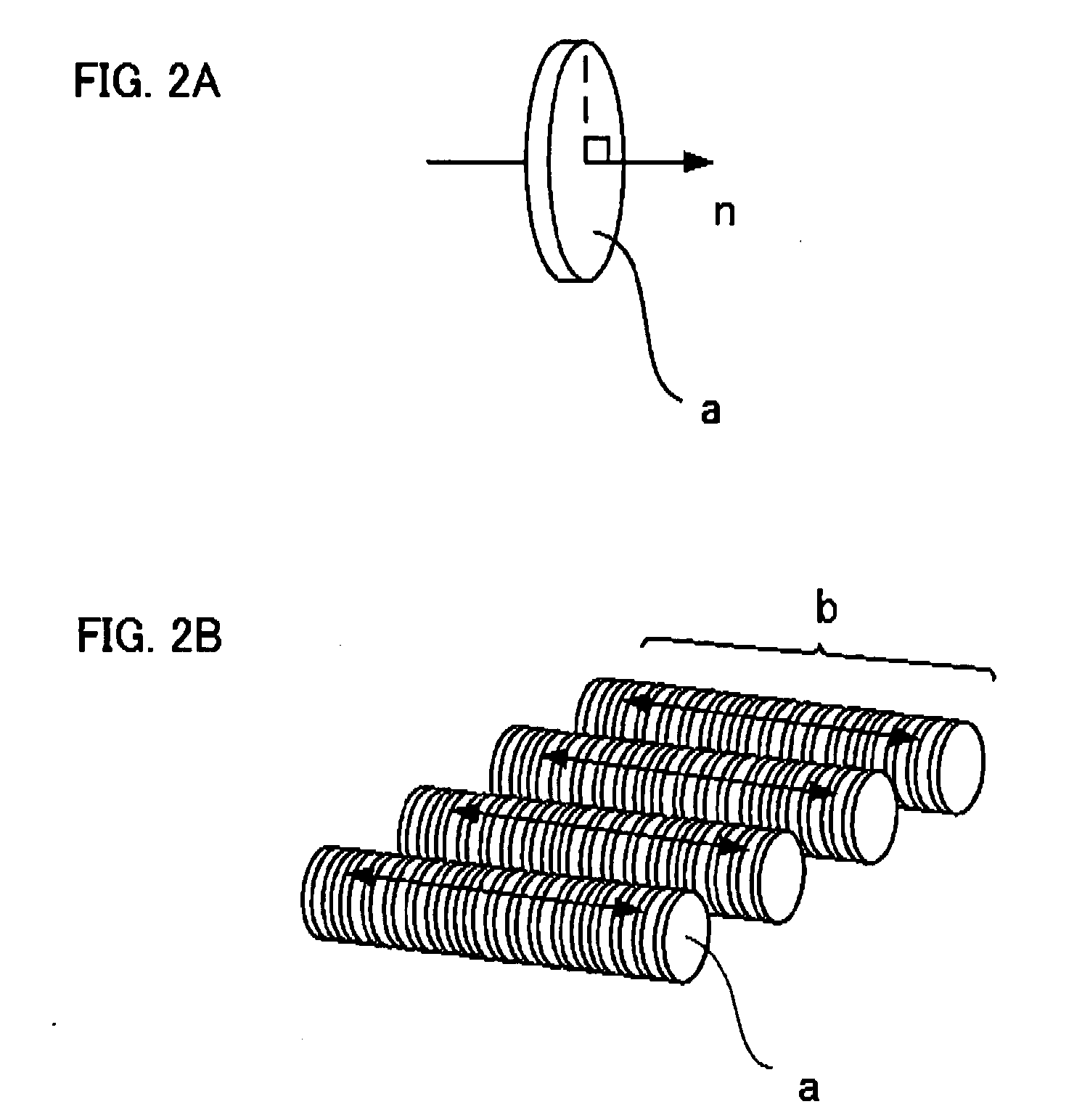
[0317] By coating with a die coater, an ink containing the plate-like molecule having the photo dichroism in the visible light range (produced by Optiva, Inc., N015) onto the ITO film of a glass substrate having an ITO electrode, washed well, and drying, it was soaked in a 15% barium chloride aqueous solution for about 1 second. By further washing and drying again, a first alignment substrate having a 0.3 μm thickness columnar alignment layer was obtained.

(Production of the Second Alignment Substrate)

[0318] A 0.3 μm thickness columnar alignment layer was formed on the ITO film of a glass substrate having an ITO electrode, washed well by the method mentioned above. Then, a solution produced by dissolving in a cyclopentanone the compound (A) to have the 2% by weight concentration was spin coated onto the columnar alignment layer by 4,000 rpm for 30 second...

example 2

(Formation of the Concave Part Pattern)

[0320] An ultraviolet ray curable acrylate resin of the below-mentioned composition was spin coated onto a glass substrate having an ITO electrode, washed well. With a concave part forming substrate having the ruggedness formed by the electron beam drawing method placed thereon, a 100 kg / cm2 load was applied for 1 minute. After directing an ultraviolet ray by 100 mJ / cm2 in this state and removing the concave part forming substrate, an ultraviolet ray was directed by 3,000 mJ / cm2 so as to form a concave part pattern in a stripe form having a 0.2 μm width, a 0.4 μm pitch and a 0.2 μm depth. By applying the plasma process thereto, the hydrophilic process was carried out on the surface.

(Composition of the ultraviolet ray curable acrylate resin)Gohselac UV-7500B (produced by Nippon40 parts by weightSynthetic Chemical Industry Co., Ltd.)1,6-hexane diol acrylate (produced35 parts by weightby NIPPON KAYAKU CO., LTD)Pentaerythritol acrylate (produce...

example 3

[0324] With the same conditions as in the example 1, a test cell was produced. A liquid crystal prepared by mixing 5% by mass of a polymerizable monomer (produced by DAINIPPON INK AND CHEMICALS, Inc. UCL-001) to a ferroelectric liquid crystal (produced by AZ Electronic Materials, R2301) was injected into the test cell by the about 100° C. temperature condition and cooled down the same gradually. Thereafter, by the exposure with a non polarized ultraviolet ray by about 1,000 mJ / cm2, the polymerizable monomer was polymerized. In the liquid crystal display obtained accordingly, a mono domain even alignment was obtained.


PUM

PropertyMeasurementUnit
widthaaaaaaaaaa
widthaaaaaaaaaa
thicknessaaaaaaaaaa

Abstract

The main object of the present invention is to control the alignment of the ferroelectric liquid crystal by a simple method without the need of an alignment process such as the rubbing process and the photo alignment process in a liquid crystal display using a ferroelectric liquid crystal; to solve better the light scattering generated at the interface between the polarizing plate and the other functional layers compared with the case of separately providing the polarizing plate by the use of an alignment layer having the alignment function of controlling the alignment of the ferroelectric liquid crystal and the polarizing function of changing a non polarized light beam to a linear polarized light beam and thereby restrain the deterioration of the light transmittance, to achieve a thin shape and a light weight of the liquid crystal display. The invention achieves the object by using a columnar alignment layer having a column structure with plate-like molecule having the photo dichroism in the visible light range as one of the alignment layers for controlling the alignment of the ferroelectric liquid crystal and forming a reactive liquid crystal layer produced by fixing a reactive liquid crystal including a polymerizable liquid crystal material on the side to be contacted with the ferroelectric liquid crystal on the columnar alignment layer, showing the nematic phase on the columnar alignment layer.

Description

BACKGROUND OF THE INVENTION [0001] 1. Field of the Invention [0002] The present invention relates to liquid crystal display using ferroelectric liquid crystal. [0003] 2. Description of the Related Art [0004] Since liquid crystal display has features that it is thin and is low in power consumption and other features, the use has been expanding in various articles from large-sized displays to portable information terminals and the development has been actively made. Conventionally, for liquid crystal display, a TN system, an STN multiplex driving system, an active matrix driving system in which thin film transistor (hereinafter, it may be referred to as “TFT element”) are used in TN, and others have been developed and made practicable. However, nematic liquid crystal is used therein; therefore, the response speed of the liquid crystal material is as small as several milliseconds to several tens of milliseconds and it cannot be said that these sufficiently cope with display of moving i...

Claims


Application Information

Patent Timeline
Patent Type & Authority Applications(United States)
IPC IPC(8): G02F1/1333G02F1/1337C09K19/52C09K19/00C09K19/38
CPCC09K19/0225C09K2019/0448G02F1/133528G02F1/133788Y10T428/1005G02F2001/133726Y10T428/1036Y10T428/10G02F1/141C09K2323/00C09K2323/02C09K2323/03G02F1/133726
Inventor OKABE, MASATOSAWATARI, NAOKOISHIKAWA, MAKOTO
Owner DAI NIPPON PRINTING CO LTD
Why Eureka
Try Eureka