Liquid crystal display device with a light diffusion layer in the reflection region alone

a liquid crystal display device and light diffusion layer technology, applied in non-linear optics, instruments, optics, etc., can solve the problems of large power consumption, deformation of visibility, and approximately 50% or more of back light power consumption, and achieve easy and accurate control, easy formation, and simplified fabrication process of liquid crystal display devices

Inactive Publication Date: 2005-05-17
SHARP KK
View PDF11 Cites 35 Cited by
  • Summary
  • Abstract
  • Description
  • Claims
  • Application Information

AI Technical Summary

Benefits of technology

[0009]An object of the invention is providing a transmission / reflection type liquid crystal display device capable of realizing high quality display in which the thickness of a liquid crystal layer, in a reflection region in particular, can be precisely controlled.

Problems solved by technology

Since a transmission type liquid crystal display displays an image by using light from a back light, it can advantageously display bright images with a high contrast ratio without being affected by ambient brightness but disadvantageously consumes large power due to the back light included therein.
A back light consumes approximately 50% or more of the power consumption in a general transmission type liquid crystal display device.
Furthermore, in a very bright environment (for example, in the open air in fine weather), the visibility is degraded or the power consumption is further increased when the brightness of the back light is increased to attain sufficient visibility.
On the other hand, since a reflection type liquid crystal display device does not include a back light, it advantageously consumes very small power, but the brightness and the contrast ratio of display are disadvantageously largely affected by the environment such as ambient brightness.
In particular, in a dark environment, the visibility is excessively degraded.
Moreover, the disadvantage of a transmission type liquid crystal display device that the visibility is degraded in a very bright environment (for example, in the open air in fine weather) can be suppressed.
Accordingly, the thickness of a liquid crystal layer is largely varied in a reflection region, and hence, it is difficult to realize optimal display.
Furthermore, it is necessary to precisely control the shape of the irregularities (convexes / concaves) for preventing light interference caused by the irregularities, which disadvantageously increases the fabrication cost.

Method used


Image

  • Liquid crystal display device with a light diffusion layer in the reflection region alone
  • Liquid crystal display device with a light diffusion layer in the reflection region alone
  • Liquid crystal display device with a light diffusion layer in the reflection region alone

Examples


embodiment 1

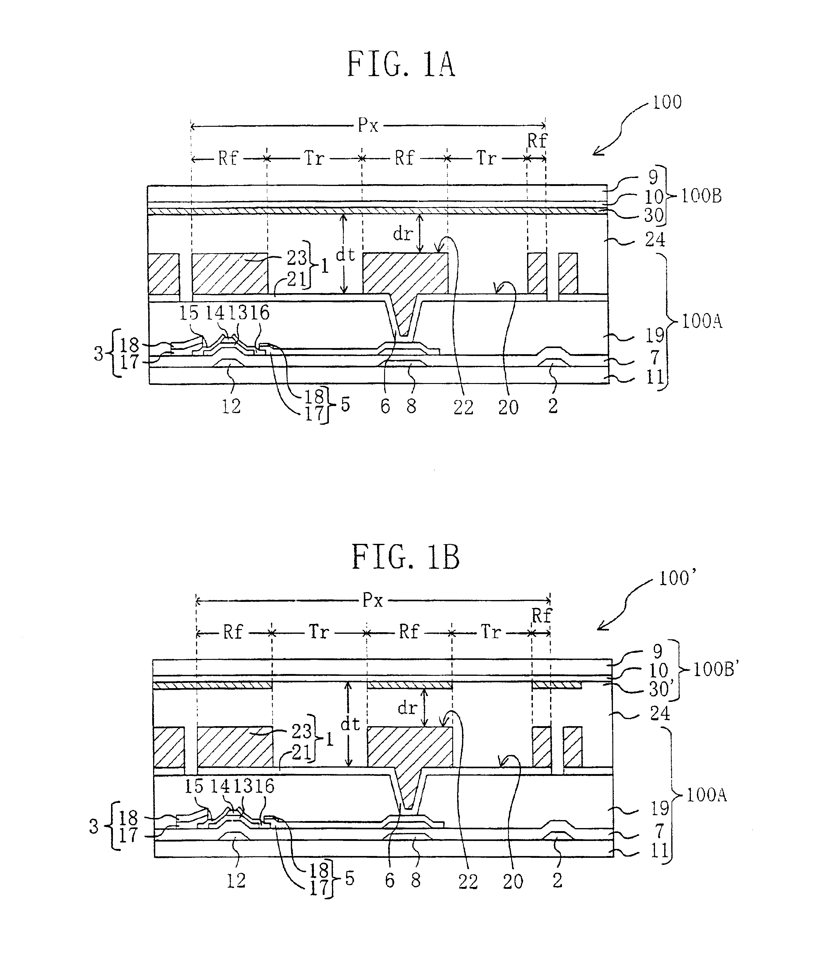
[0044]In a liquid crystal display device of Embodiment 1, a light diffusion layer is disposed on the inside (on a side closer to a liquid crystal layer) of a second substrate (disposed on a side closer to an observer) opposing a first substrate (disposed on a side closer to a back light) with the liquid crystal layer sandwiched therebetween.

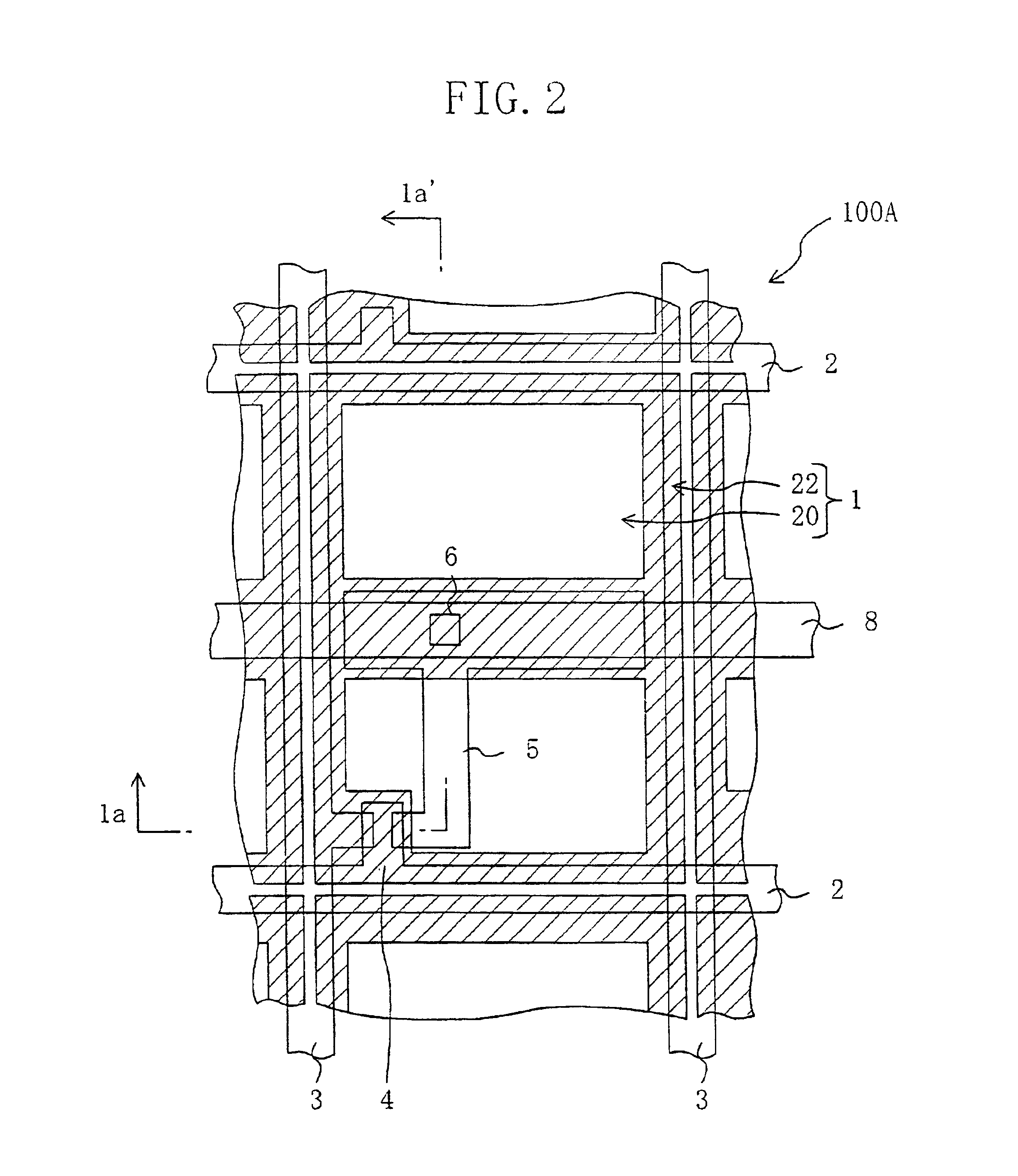
[0045]FIGS. 1A and 1B respectively show the schematic sectional structures of liquid crystal display devices 100 and 100′ of this embodiment. FIGS. 1A and 1B are cross-sectional views of the liquid crystal display devices 100 and 100′ of this embodiment, and FIG. 2 is a plan view of an active matrix substrate 100A used in the liquid crystal display devices 100 and 100′.

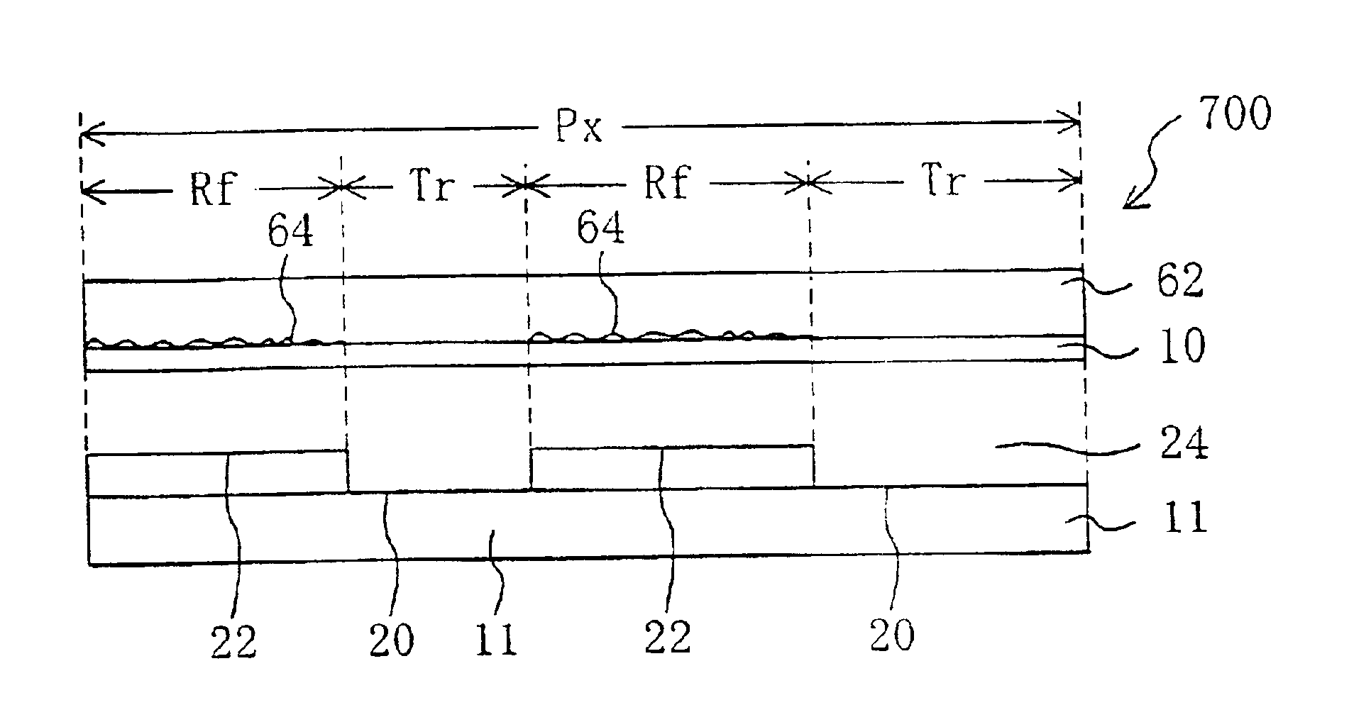
[0046]Each of the transmission / reflection type liquid crystal display devices 100 and 100′ includes, as is shown in FIGS. 1A and 1B, a transmission region Tr and a reflection region Rf in each of plural pixel regions Px arranged in the form of a matrix, so as to display images in a...

embodiment 2

[0090]A liquid crystal display device according to Embodiment 2 is different from the liquid crystal display devices of Embodiment 1 in including a light diffusion layer disposed on the outside of a second substrate (a side closer to an observer) opposing a first substrate (closer to a back light) with a liquid crystal layer sandwiched therebetween. In drawings showing liquid crystal display devices of Embodiment 2, the same reference numerals are used to refer to elements substantially having the same functions as those used in the liquid crystal display devices of Embodiment 1 so as to omit the description.

[0091]FIGS. 12A and 12B respectively show the schematic sectional structures of the liquid crystal display devices 1000 and 1000′ of Embodiment 2. The liquid crystal display devices 1000 and 1000 of FIGS. 12A and 12B are respectively different from the liquid crystal display devices 200 and 200′ of FIGS. 4A and 4B in disposing the light diffusion layer 30 on the outside (a side ...

embodiment 3

[0100]A liquid crystal display device according to Embodiment 3 is similar to the liquid crystal display devices of Embodiment 2 in disposing a light diffusion layer on the outside (a side closer to an observer) of a second substrate (closer to the observer), but is different in further including an anti-glare layer on the outside of the second substrate. In drawings showing liquid crystal display devices of Embodiment 3, the same reference numerals are used to refer to elements having substantially the same functions as those of the liquid crystal display devices of Embodiment 1 and 2 so as to omit the description. Also, detailed description of the structures of the transparent electrode region 20 and the reflection electrode region 22 is omitted for simplification.

[0101]FIG. 15 is a schematic sectional view of a liquid crystal display device 1300 of Embodiment 3. The liquid crystal display device 1300 of FIG. 15 is obtained by providing an anti-glare layer 94 on the surface closer...


PUM

PropertyMeasurementUnit
heat resistanceaaaaaaaaaa
particle sizeaaaaaaaaaa

Abstract

Each pixel region includes a transmission region for display in a transmission mode using light entering through a first substrate and a reflection region for display in a reflection mode using light entering through a second substrate. The first substrate includes a transparent electrode region and a reflection electrode region, both of which have flat surfaces facing a liquid crystal layer. The second substrate includes a transparent electrode in the reflection region and the transmission region on its surface facing the liquid crystal layer and includes a light diffusion layer in the reflection region, and the surface facing the liquid crystal layer is flat in the transmission region and the reflection region.

Description

BACKGROUND OF THE INVENTION[0001]The present invention relates to a liquid crystal display device, and more particularly, it relates to a transmission / reflection type liquid crystal display device capable of display in both a transmission mode and a reflection mode.[0002]Owing to their characteristics such as a small thickness and small power consumption, liquid crystal display devices are recently widely used in OA equipment such as a word processor and a personal computer, portable information equipment such as an electronic notebook and a camera-integrated VTR equipped with a liquid crystal monitor.[0003]The liquid crystal display devices are divided roughly into two types: reflection type and transmission type. A liquid crystal display device is not a spontaneously luminous display device like a CRT (cathode-ray tube) and EL (electroluminescence), but light of a lighting device disposed behind a liquid crystal display panel (known as the so-called back light) is used for display...

Claims


Application Information

Patent Timeline
Patent Type & Authority Patents(United States)
IPC IPC(8): G02F1/1335G02F1/13G02F1/1333G02F1/1343
CPCG02F1/133555G02F1/133371G02F2001/133565G02F1/133504G02F1/133565G02F1/1335
Inventor FUJIMORI, KOICHIKUBO, MASUMINARUTAKI, YOZO
Owner SHARP KK
Why Eureka
Try Eureka