Lighting Device

a lighting device and a technology of a light source, applied in the direction of gas discharge lamp usage, climate sustainability, light sources, etc., can solve the problems of difficult to make the minimum operating voltage of the control ics equal, same events can also occur, etc., to achieve highly reliable lighting devices, avoid the effect of failures

Inactive Publication Date: 2013-02-28
EYE LIGHTING SYST CORP
View PDF1 Cites 5 Cited by
  • Summary
  • Abstract
  • Description
  • Claims
  • Application Information

AI Technical Summary

Benefits of technology

[0016]The present invention has been made in view of the foregoing problems, where, when a lighting device has a plurality of switching circuits, a driving circuit is provided for each of the switching circuits to drive it, and the driving circuits have different operating voltages from each other; the driving circuits may start and stop operating in a random order or the driving circuits may operate in unstable manner. An object of the present invention is to provide a lighting device capable of starting or stopping driving circuits for switching elements in a desired order and of operating the driving circuits in a stable manner.
[0022]As described above, according to the present invention, since the detection means and judging means are provided, the driving circuits, such as control ICs or drivers, can be activated in a desired order after a stable driving voltage equal to or larger than the predetermined value is obtained when the driving voltage for the driving circuits rises upon turning on the power or in other situations. In addition, all of the driving circuits can be stopped in a desired order within a period during which the driving voltage is maintained at the predetermined value or more when the driving voltage for the driving circuits falls when the power is interrupted or in other situations. Therefore, the driving circuits are prevented from being activated or stopped in a random order. Since the driving circuits are reliably activated and stopped in a condition where stable operating voltages are obtained, the driving circuits are prevented from malfunctioning. Unstable operation of the driving circuits caused by insufficient driving voltages is eliminated, and circuit failure does not easily occur. A highly reliable lighting device can be provided.
[0023]The present invention is effective not only when turning on and interrupting the external power source but also when the external power source fluctuates or when the remaining battery capacity decreases during the time when the light source is on. For example, when the driving voltage for the driving circuits becomes lower than the predetermined value due to fluctuation of the external power source, the driving circuits can be stopped reliably in the same way as when the power source is interrupted. When the driving voltage is restored to the predetermined value or more, the driving circuits can be activated reliably in the same way as when the power source is turned on. Therefore, even if the external power source fluctuates, starting and stopping of the driving circuits can be appropriately controlled. The driving circuits are prevented from being activated or stopped in a random manner, and are also prevented from malfunctioning.

Problems solved by technology

When the plurality of control ICs operate with the common control voltage, they may be activated not in a desired order but in a random order, or they may operate in an unstable manner even if they are activated, causing circuit failure.
However, since the control ICs are designed according to the functions and characteristics of the corresponding circuit blocks, it is very difficult to make the minimum operating voltages of the control ICs equal.
This unstable operation of the control ICs and the random-order stopping of the control ICs are considered as causes of circuit failure.
In addition, the same events can also occur if the voltage drops due to fluctuation of the external power source or if the remaining battery capacity is low.
Therefore, as described above, the control ICs may start and stop operating in a random order or the control ICs may operate in an unstable manner.
The same problems occur also when drivers are used to drive the switching circuits.

Method used


Image

  • Lighting Device
  • Lighting Device
  • Lighting Device

Examples


Embodiment Construction

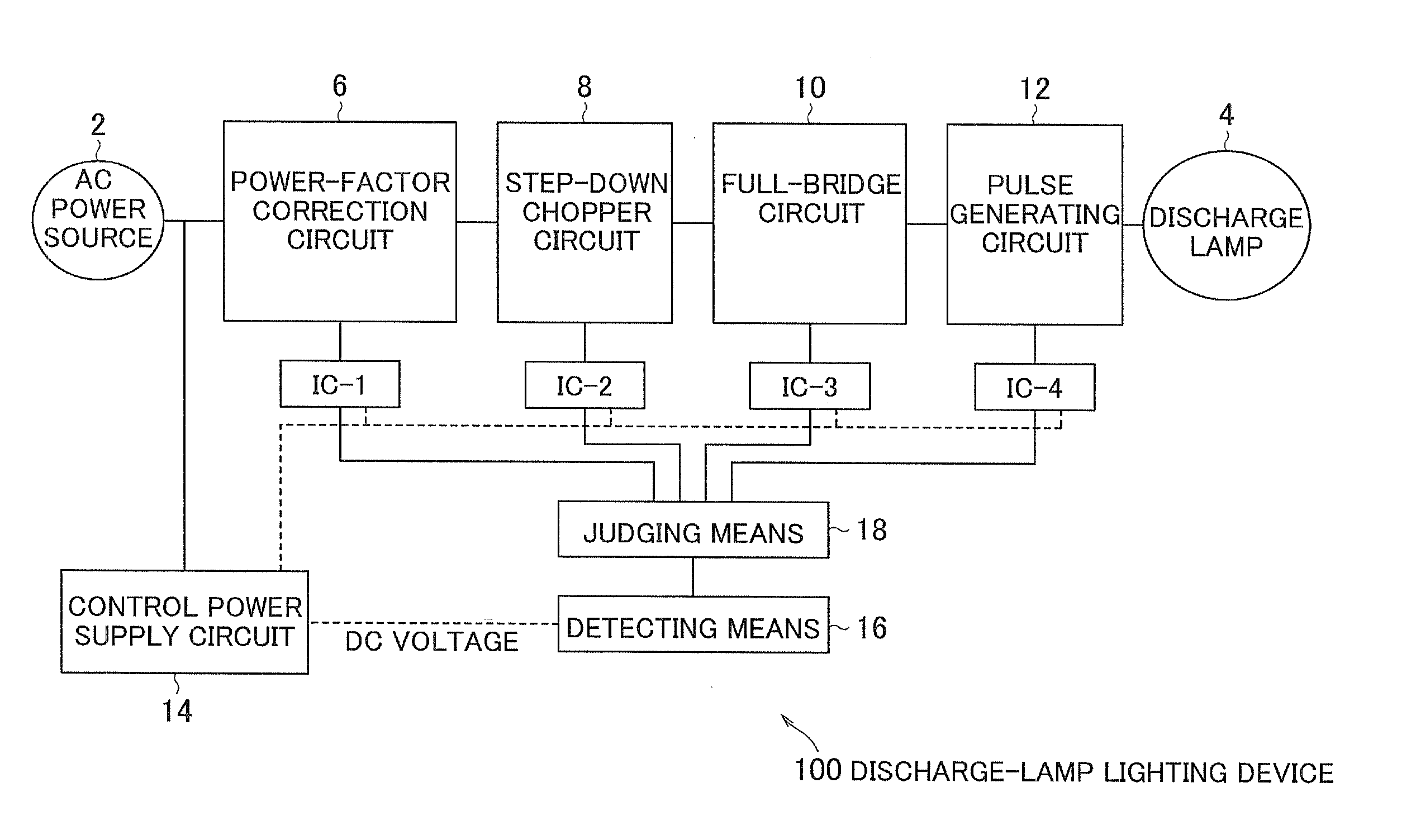
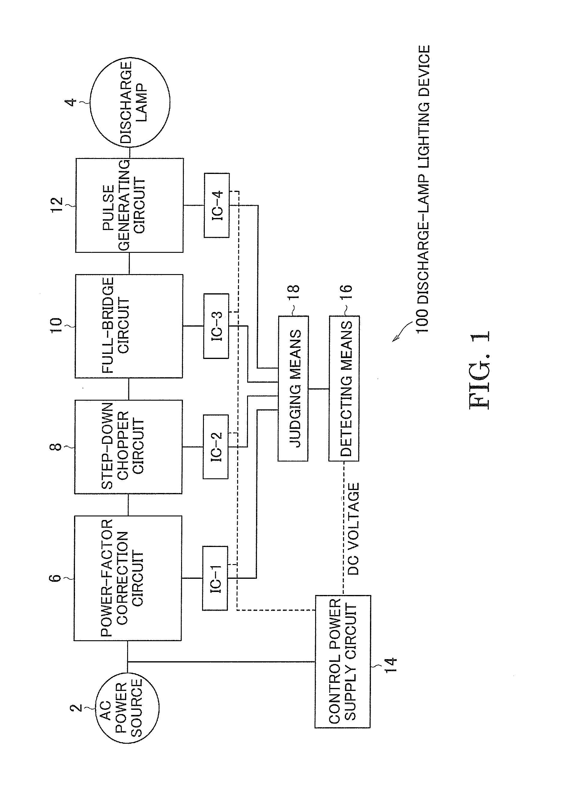
[0030]FIG. 1 is a view showing the entire configuration of a discharge-lamp lighting device 100 of the present invention. As shown in the figure, in the same way as the conventional discharge-lamp lighting device shown in FIG. 5, the discharge-lamp lighting device 100 also includes a power-factor correction circuit 6, a step-down chopper circuit 8, a full-bridge circuit 10, and a pulse generating circuit 12. A description will be omitted for components common to those shown in FIG. 5. The configuration shown in FIG. 1 is just an example configuration of a lighting device of the present invention. The present invention also encompasses lighting devices having different configurations. For example, the present invention encompasses a discharge-lamp lighting device that uses a full-bridge step-down chopper circuit or a half-bridge step-down chopper circuit, both of which have the function of a step-down chopper circuit and the function of a full-bridge circuit. The present invention al...


PUM


Abstract

A lighting device has a power-factor correction circuit 6, a step-down chopper circuit 8, a full-bridge circuit 10, control ICs for these circuits and a driving-voltage supply circuit 14. The supply circuit 14 supplies a driving voltage to the control ICs. The control IC outputs the on / off driving voltage to a switching element of the corresponding circuit 6 to 10. The lighting device also has a detector 16 and judgment equipment 18. The detector 16 detects the driving voltage supplied from the supply circuit 14. The judgment equipment 18 instructs the control ICs to start outputting the on / off driving voltages in the order from the control IC close to the power source 2 to the control IC close to the discharge lamp 4 when the driving voltage detected by the detector 16 reaches a predetermined value during the time when the driving voltage supplied from the supply circuit 14 rises.

Description

CROSS-REFERENCE TO RELATED APPLICATIONS[0001]This application is based on and claims the benefits of priority from Japanese Patent Application No. 2011-183369, filed on Aug. 25, 2011, the entire contents of which are incorporated herein by reference.BACKGROUND OF THE INVENTION[0002]1. Field of the Invention[0003]The present invention relates to lighting devices such as a discharge-lamp lighting device and an LED lighting device, and more particularly, to start and stop control of a control IC, a driver, or another driving circuit for driving a switching element used in a lighting device.[0004]2. Description of the Related Art[0005]Since inverters can easily output a high frequency rectangular signal, they are used in lighting devices for high intensity discharge (HID) lamps. They are also used in direct-current power supply circuits that light LED light sources. In inverters, many switching elements such as power MOS FETs, which can be driven at high frequency, are used, and special...

Claims


Application Information

Patent Timeline
Patent Type & Authority Applications(United States)
IPC IPC(8): H05B37/02
CPCH05B41/28Y02B20/186H05B41/2853Y02B20/00
Inventor UMEZAWA, YOSHIHISAKANEKO, KENSUKE
Owner EYE LIGHTING SYST CORP
Why Eureka
Try Eureka