Rechargeable battery

Active Publication Date: 2013-03-07
ROBERT BOSCH GMBH +1
View PDF6 Cites 14 Cited by
  • Summary
  • Abstract
  • Description
  • Claims
  • Application Information

AI Technical Summary

Benefits of technology

[0032]According to an embodiment of the present invention, because a short-circuit protrusion is formed at the bottom of each of the terminals, the positive electrode and the negative electrode can be easily short-circuited at a

Problems solved by technology

If pressure rises due to an abnormal reaction within the rechargeable battery having

Method used


Image

  • Rechargeable battery
  • Rechargeable battery
  • Rechargeable battery

Examples


first embodiment

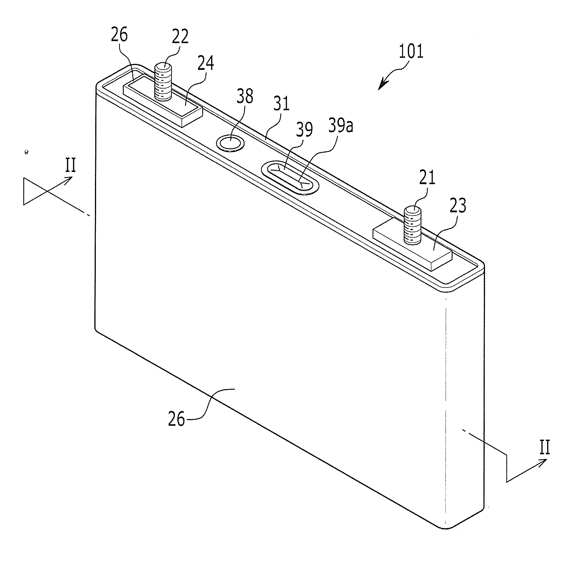
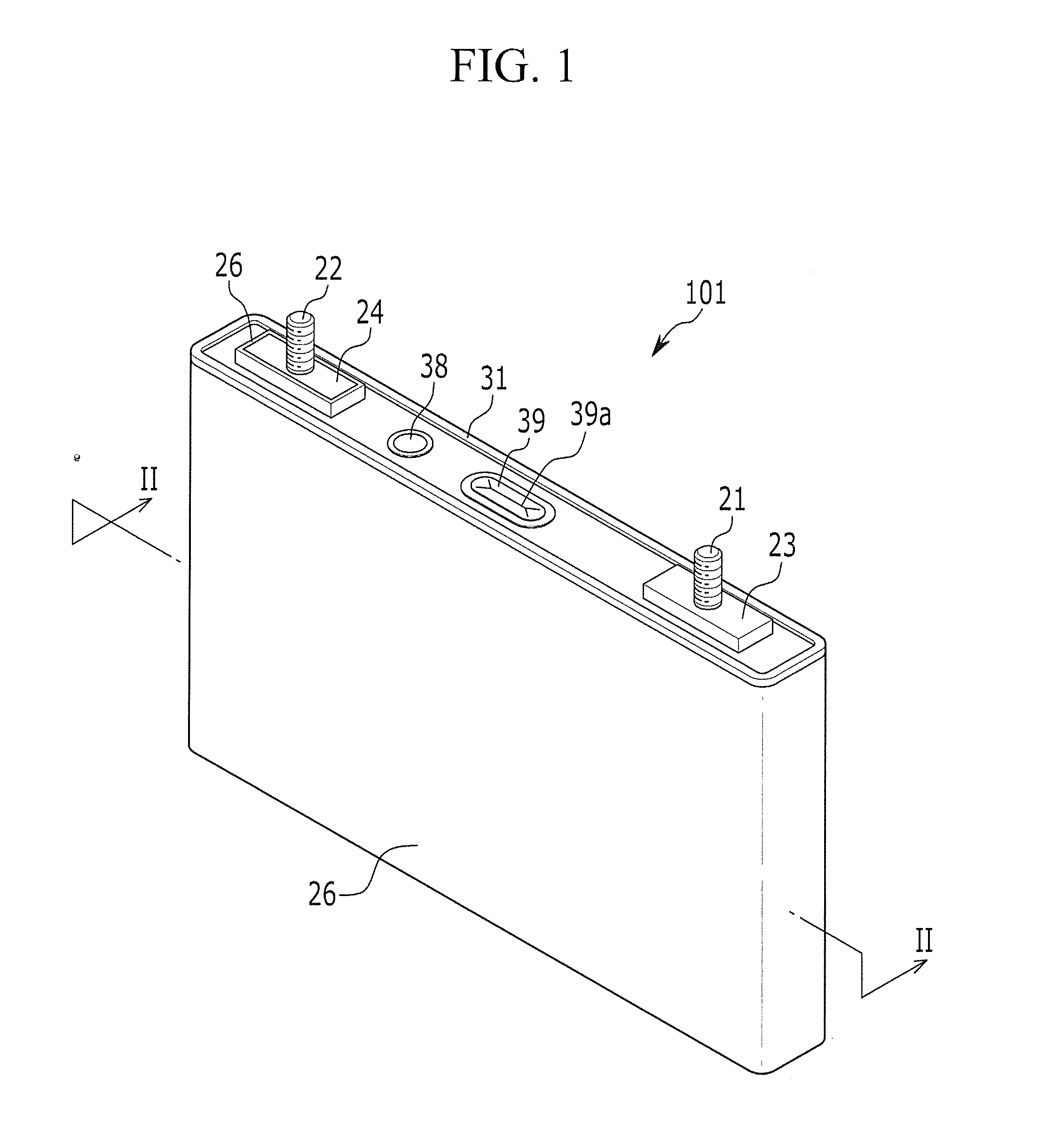
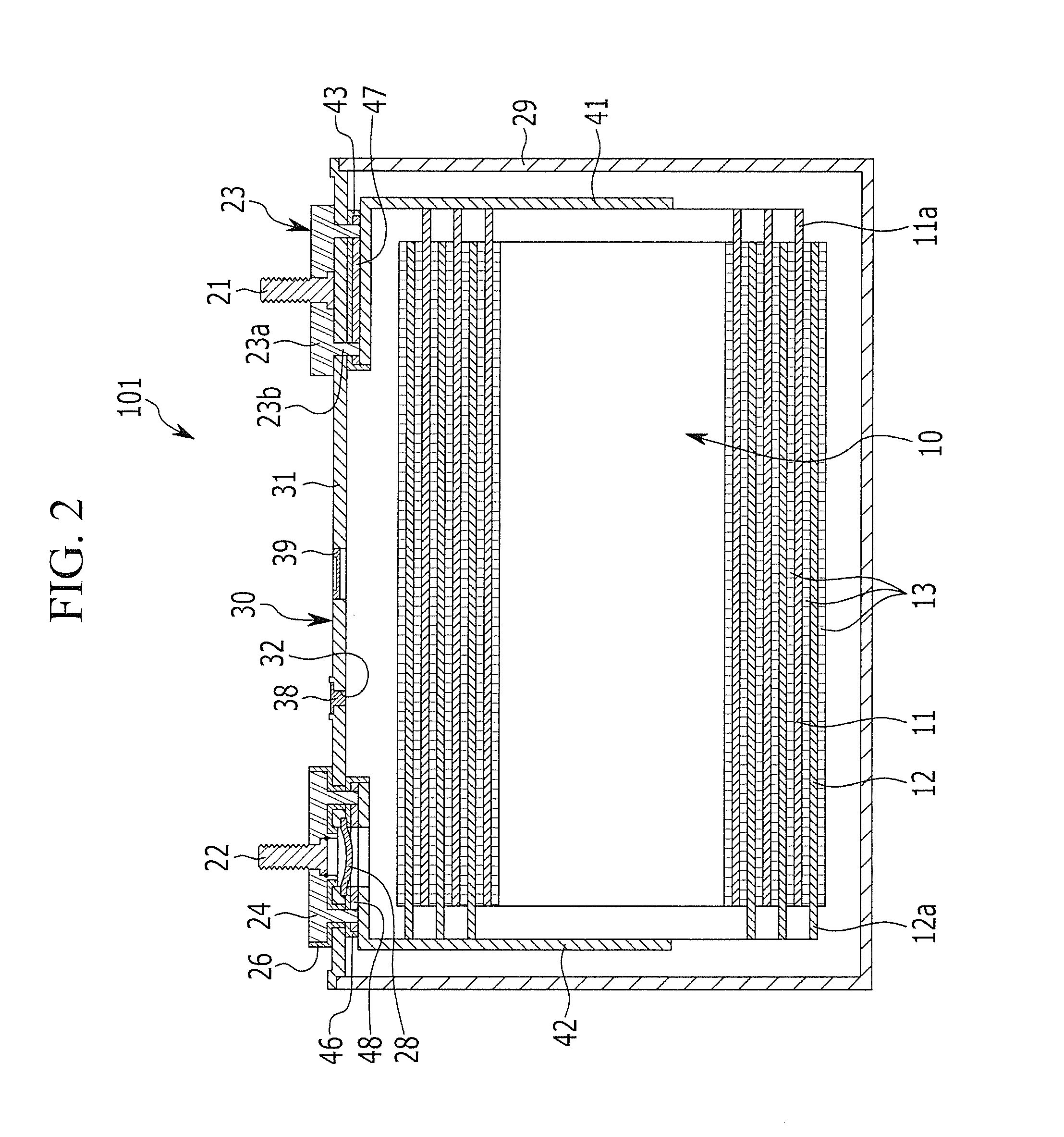
[0045]FIG. 1 is a perspective view illustrating a rechargeable battery according to the present invention, and FIG. 2 is a cross-sectional view of the rechargeable battery of FIG. 1 taken along line II-II of FIG. 1.

[0046]Referring to FIG. 1 and FIG. 2, a rechargeable battery 100 according to a first embodiment of the present invention includes: an electrode assembly 10 that is spiral-wound by stacking (or sandwiching) a separator 13 between a positive electrode 11 and a negative electrode 12; a case 29 housing the electrode assembly 10; and a cap assembly 30 that is coupled to an opening of the case 29.

[0047]The rechargeable battery 100 according to the first embodiment is a lithium ion rechargeable battery and has a quadrangular shape. However, embodiments of the present invention are not limited thereto, and the present invention can be applied to various forms of batteries such as a lithium polymer battery or a cylindrical battery.

[0048]The positive electrode 11 and the negative ...

second embodiment

[0077]FIG. 5 is an exploded perspective view illustrating a second terminal and an upper insulating member according to the present invention, and FIG. 6 is a transverse cross-sectional view of the upper insulating member taken along line VI-VI of FIG. 5.

[0078]Referring to FIG. 5 and FIG. 6, the rechargeable battery according to the embodiment illustrated in FIG. 5 and FIG. 6 may have the same structure as the rechargeable battery according to the first embodiment illustrated in FIGS. 1, 2, 3, and 4 as described above, except for the structure of the second terminal 125 and the upper insulating member 126, so a repeated description of substantially similar structures will be omitted.

[0079]The second terminal 124 includes an upper support portion 124a formed in a plate shape and fixing portions 124b protruding downward from the upper support portion 124a. The upper support portion 124a has a hole 124d in which a connecting terminal 122 is inserted, and a short-circuit protrusion 124c...

third embodiment

[0086]FIG. 7 is a cross-sectional view illustrating a rechargeable battery according to the present invention.

[0087]Referring to FIG. 7, the rechargeable battery according to the third embodiment of the present invention may have a substantially similar structure as the rechargeable battery according to the first embodiment as described above, except for the structure of the second terminal 223 and the upper insulating member 224, so a repeated description of substantially similar structures will be omitted.

[0088]The rechargeable battery 102 according to the third embodiment has a cap assembly 30 including a cap plate 31, a first terminal 223, and a second terminal 224.

[0089]The first terminal 223 has a plate portion 223a and fixing portions 223b protruding downward from the plate portion 223a. The fixing portions 223b extend through the cap plate 31, the lower insulating member 43, the support plate 47, and the first current collecting member 241, and are riveted to the support pla...


PUM


Abstract

A rechargeable battery includes: an electrode assembly including a first electrode having a first polarity and a second electrode having a second polarity, the second polarity being different from the first polarity; a case housing the electrode assembly; a first terminal electrically connected to the first electrode; a cap plate coupled to an opening of the case; a first lower insulating member between the first electrode and the cap plate; and a first short-circuit member between the first terminal and the first lower insulating member, and configured to be deformed to electrically connect the first electrode to the cap plate, wherein the first terminal includes a first fixing portion electrically connected to the first electrode.

Description

CROSS-REFERENCE TO RELATED PATENT APPLICATION[0001]This application claims priority to and the benefit of U.S. Provisional Patent Application No. 61 / 531,499 filed on Sep. 6, 2011, in the United States Patent and Trademark Office, the disclosure of which is incorporated herein in its entirety by reference.BACKGROUND[0002]1. Field[0003]The described technology relates generally to a rechargeable battery. More particularly, the described technology relates generally to a rechargeable battery having an improved terminal structure.[0004]2. Description of Related Art[0005]A rechargeable battery can be recharged and discharged, unlike a primary battery that cannot be recharged. A rechargeable battery with low capacity is often used for a small portable electronic device such as a mobile phone, a laptop computer, and a camcorder, while a rechargeable battery with large capacity is typically used as a power source for driving a motor such as for a hybrid electric vehicle.[0006]Recently, a la...

Claims


Application Information

Patent Timeline
IPC IPC(8): H01M2/00H01M50/147H01M50/528H01M50/531H01M50/55H01M50/553H01M50/566H01M50/567
CPCH01M2/043H01M2200/20H01M2/345H01M2/305Y02E60/10H01M50/147H01M50/578Y02P70/50H01M50/55H01M50/531H01M50/567H01M50/553H01M50/566H01M10/0413H01M50/543H01M50/528H01M50/579
Inventor KIM, DUK-JUNG
Owner ROBERT BOSCH GMBH
Why Eureka
Try Eureka