Light source device and projector

a light source device and projector technology, applied in the direction of projectors, instruments, optics, etc., can solve the problems of shortening the life of the projector, and affecting the performance of the projector

Inactive Publication Date: 2013-05-02
HON HAI PRECISION IND CO LTD
View PDF5 Cites 20 Cited by
  • Summary
  • Abstract
  • Description
  • Claims
  • Application Information

AI Technical Summary

Problems solved by technology

However, the light sources of such light source devices not only lead to a complex and bulky design of the internal structure of the projector, but also causes a build up of heat,

Method used


Image

  • Light source device and projector
  • Light source device and projector
  • Light source device and projector

Examples


Embodiment Construction

[0010]The disclosure is illustrated by way of example and not by way of limitation in the figures of the accompanying drawings in which like references indicate similar elements. It should be noted that references to “an” or “one” embodiment in this disclosure are not necessarily to the same embodiment, and such references mean at least one.

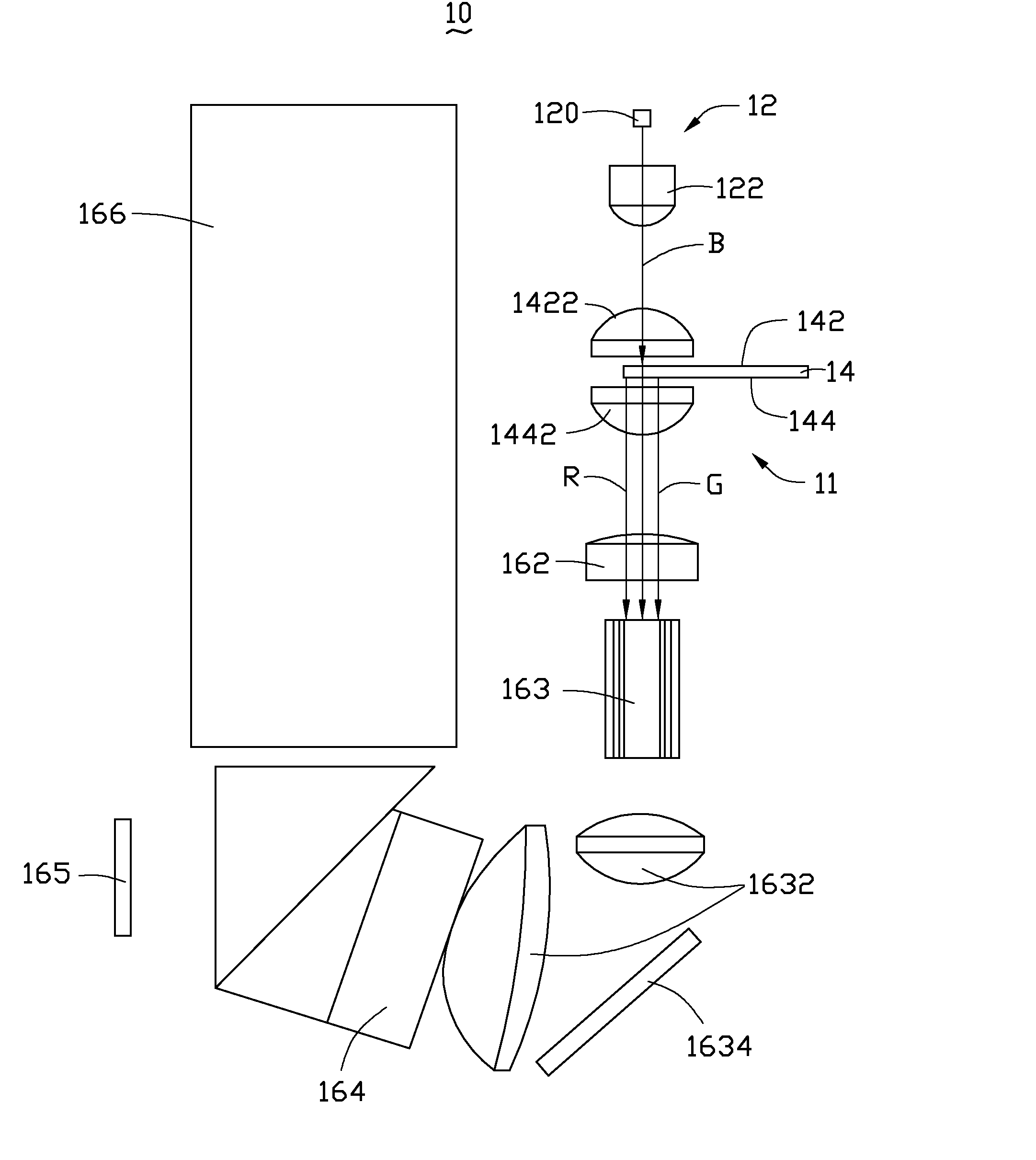
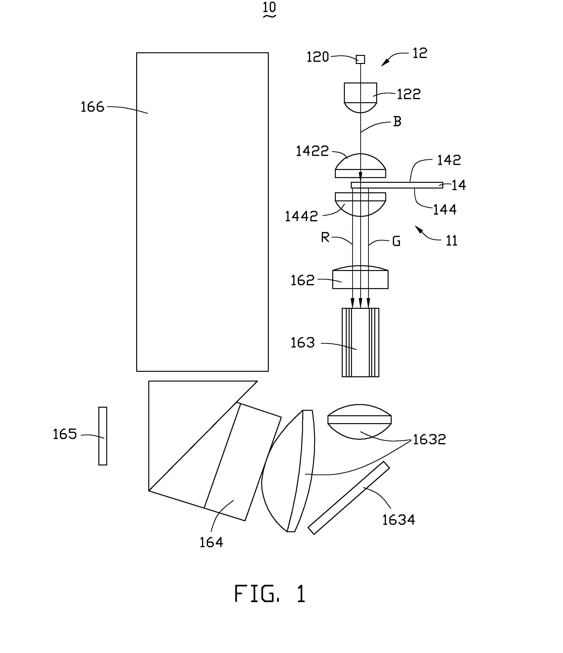
[0011]According to one embodiment, a projector 10 as illustrated in FIG. 1 includes a light source device 11, a light merging unit 162, a light guide unit 163, a prism unit 164, a digital micro-mirror device (DMD) 165, and a projection lens set 166. The projector 10 also comprises a mirror 1634 and a number of lenses 1632, 1422, and 1442. The light source device 11 and the projection lens set 166 are positioned at two sides of the projector 10. In one embodiment, the light guide unit 163 is a light tunnel. The prism unit 164 is a reverse total internal reflection (TIR) prism including two prisms combined together.

[0012]The light source device 11 ...


PUM


Abstract

A projector includes a projection lens set, a digital micro-mirror device, a prism unit, a light merging unit, a light guide unit, and a light source device. The light source device includes a laser light source and a color wheel. The laser light source is positioned in a straight optical path and generates a first light. The color wheel is positioned in the straight optical path. The first light irradiates the color wheel to generate a second light and the third light. The light merging unit merges the first, second, and third lights to generate a mixed light. The light guide unit guides the mixed light to the prism unit. The mixed light is refracted to the DMD via the prism unit, and then the refracted mixed light is reflected to the projection lens set via the DMD.

Description

BACKGROUND[0001]1. Technical Field[0002]The present disclosure relates to a light source device and a projector having a light source device.[0003]2. Description of Related Art[0004]Heightened requirements are imposed on the imaging quality of projectors. A projection system primarily includes a light source device and a projection lens set. Emphasis has been put on improving the arrangement reliability of components, to shrink the overall volume and increase the light source efficiency in the light source device to enhance the imaging brightness in the back-end projection lens set.[0005]To improve the image brightness, a conventional projector utilizes a number of light sources to provide various color lights. However, the light sources of such light source devices not only lead to a complex and bulky design of the internal structure of the projector, but also causes a build up of heat, exacerbated by poor heat dissipation. After a period of operation, the high temperatures tend to...

Claims


Application Information

Patent Timeline
IPC IPC(8): G03B21/14
CPCG03B21/204
Inventor HSU, CHIEN-WENYEH, WEN-PIN
Owner HON HAI PRECISION IND CO LTD
Why Eureka
Try Eureka