Interference microscope system based on programmable illumination

A technology of interference microscope and illumination light source, which is applied in the field of interference microscope, can solve the problems of interference pattern distortion, difference of incident light reflectivity, and influence on the measurement accuracy of interference microscope, and achieve the effect of good three-dimensional shape and guaranteed accuracy

Inactive Publication Date: 2014-08-13
UNIV OF SHANGHAI FOR SCI & TECH
View PDF7 Cites 16 Cited by
  • Summary
  • Abstract
  • Description
  • Claims
  • Application Information

AI Technical Summary

Problems solved by technology

However, due to the diversity of the measured objects, there may be huge differences in the reflectivity of different areas for incident light
When using a uniform illumination structure, the difference in the optical properties of different areas on the surface will lead to the distortion of the final interferogram, resulting in the above-mentioned various error factors, which will ultimately affect the measurement accuracy of the interference microscope

Method used


Image

  • Interference microscope system based on programmable illumination
  • Interference microscope system based on programmable illumination
  • Interference microscope system based on programmable illumination

Examples


Embodiment Construction

[0036] In order to make the technical means, creative features, goals and effects achieved by the present invention easy to understand, the present invention will be further described below in conjunction with specific diagrams.

[0037] A specific implementation method of an interference microscope system based on programmable illumination proposed by the present invention will be described below with reference to the accompanying drawings.

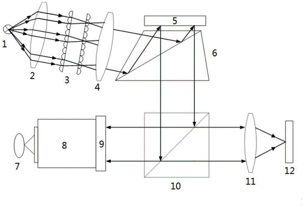
[0038] The structure of the example 1 of the present invention is as figure 1 As shown, the specific steps are:

[0039] At first the illumination source 1 can obtain collimated uniform light through the illumination module; the refraction of the obtained collimated uniform light will be incident on the digital micromirror device (DMD) 5 with 24 ° through the TIR prism 6, and this is because the DMD The deflection angle of the micro-mirror on the chip is 12°; then the "on" or "off" state of each micro-mirror is artificially controlled b...


PUM


Abstract

The invention relates to an interference microscope, in particular to an interference microscope system based on programmable illumination. The interference microscope system based on programmable illumination comprises an illumination light source, an illumination module and a digital micro mirror device, wherein the digital micro mirror device comprises a digital micro mirror array, each digital micro mirror has an n degree deflection angle state and a -n degree deflection angle state, light enters the digital micro mirror device at the incidence angle of 2n degrees through refraction and reflection of a TIR prism, then the on or off state of each micro reflection mirror is controlled, the light is subjected to corresponding spatial modulation, and then the light exits perpendicularly from the digital micro mirror device. The light path enters a Mirau interference objective mirror through reflection of a beam splitter prism, and is split into two light beams through a beam splitter in the Mirau interference objective mirror, the two light beams are irradiated to a reference plane and a detected plane and then are reflected back, and optical interference is formed in the beam splitter. An interference optical field of a detected object returns from the interference objective mirror, passes through the beam splitter prism again, and is received by a detector after passing through a barrel mirror, and an interference image of the interference microscope is obtained.

Description

technical field [0001] The invention relates to the technical field of precision measurement, in particular to an interference microscope. Background technique [0002] With the development of micro-fabrication technology, micro-circuits, micro-optical components, micro-machines and other micro-structures are emerging, and the demand for micro-structure surface topography measurement systems is becoming more and more urgent. Since the microsurface structure is a three-dimensional complex structure composed of microstructure units, its measurement generally requires direct or indirect microscopic magnification, which requires high lateral and longitudinal resolutions. At the same time, unlike the measurement of smooth surfaces, the measurement of microstructured surfaces not only measures the roughness or flaws of the surface, but also measures the contour, shape deviation and position deviation of the surface. [0003] In 1968, Williamson of the United States first develope...

Claims


Application Information

Patent Timeline
Patent Type & Authority Applications(China)
IPC IPC(8): G01B11/24G01B9/023
Inventor 万新军朱伟超杨波
Owner UNIV OF SHANGHAI FOR SCI & TECH
Why Eureka
Try Eureka