Optical receiver preamplifier
a receiver and optical technology, applied in the direction of amplifier modifications to reduce non-linear distortion, gain control, electromagnetic transceivers, etc., can solve the problems of low output voltage, waveform distortion, and small transmission loss in the fiber, so as to reduce the current-voltage conversion element and suppress the saturation of the output voltage. , the effect of current flowing
- Summary
- Abstract
- Description
- Claims
- Application Information
AI Technical Summary
Benefits of technology
Problems solved by technology
Method used
Image
Examples
first embodiment
[0069] Hereinafter, an optical receiver preamplifier according to a first embodiment of the present invention will be described with reference to the accompanying drawings.
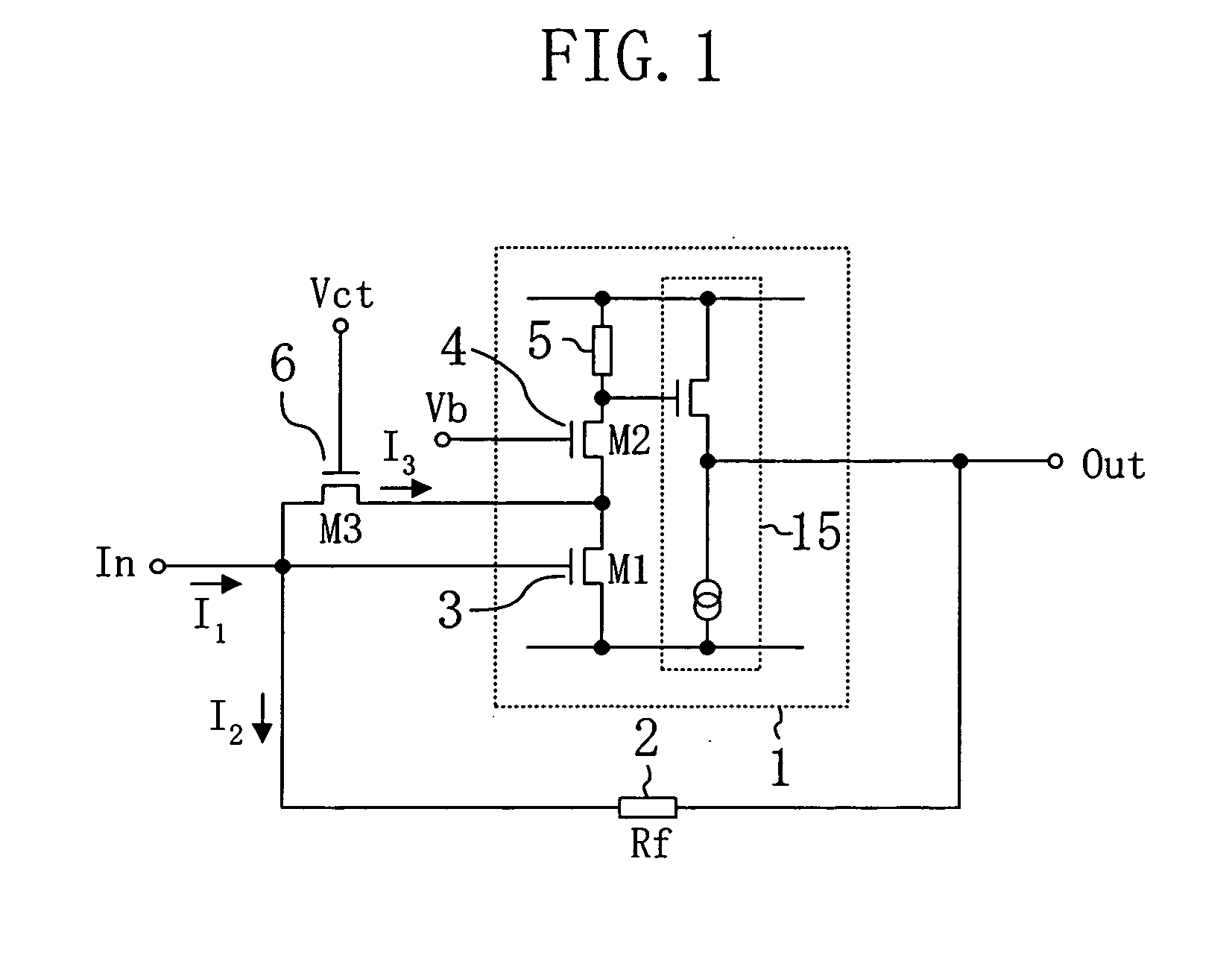
[0070]FIG. 1 illustrates a schematic configuration of the optical receiver preamplifier of the first embodiment.
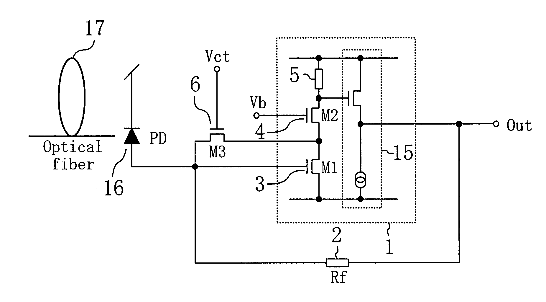
[0071] As shown in FIG. 1, the optical receiver preamplifier of the present invention is a transimpedance type preamplifier including an inverting amplifier 1 and a current-voltage conversion element (RF) 2 connected between an input terminal In and an output terminal Out of the inverting amplifier 1. In this embodiment, as the current-voltage conversion element 2, for example, a normal resistor is used.
[0072] A first feature of this embodiment is that the inverting amplifier 1 includes a first transistor (M1) 3 having a source connected to the ground and a gate connected to the input terminal In of the inverting amplifier 1, a second transistor (M2) 4 having a source connected to a drain of the first...
second embodiment
[0077] Hereinafter, an optical receiver preamplifier according to a second embodiment of the present invention will be described with reference to the accompanying drawings.
[0078]FIG. 4 illustrates a schematic configuration of the optical receiver preamplifier of the second embodiment. In FIG. 4, each member also shown in FIG. 1 of the first embodiment is identified by the same reference numeral, and therefore the description thereof will be described.
[0079] As shown in FIG. 4, the second embodiment is different from the first embodiment in that an operational amplifier 7 is provided. Specifically, the second embodiment has a configuration obtained by adding the operational amplifier 7 to the configuration of the first embodiment. In this case, an inverting input terminal of the operational amplifier 7 is connected to a source of a second transistor 4. Moreover, a non-inverting input terminal of the operational amplifier 7 is connected to an input terminal In of an inverting ampli...
third embodiment
[0084] Hereinafter, an optical receiver preamplifier according to a third embodiment of the present invention will be described with reference to the accompanying drawings.
[0085]FIG. 6 illustrates a schematic configuration of the optical receiver preamplifier of the third embodiment. In FIG. 6, each member also shown in FIG. 1 of the first embodiment is identified by the same reference numeral, and the description thereof will be described.
[0086] As shown in FIG. 6, the third embodiment is different from the first embodiment in that an operational amplifier 7 and a voltage generator circuit 8 are provided. Specifically, the third embodiment has a configuration obtained by adding the operational amplifier 7 and the voltage generator circuit 8 to the configuration of the first embodiment. In this case, an inverting input terminal of the operational amplifier 7 is connected to the source of a second transistor 4. A non-inverting input terminal of the operational amplifier 7 is connec...
PUM
 Abstract
Description
Claims
Application Information
 - R&D
- Intellectual Property
- Life Sciences
- Materials
- Tech Scout
- Unparalleled Data Quality
- Higher Quality Content
- 60% Fewer Hallucinations
Browse by: Latest US Patents, China's latest patents, Technical Efficacy Thesaurus, Application Domain, Technology Topic, Popular Technical Reports.
© 2025 PatSnap. All rights reserved.Legal|Privacy policy|Modern Slavery Act Transparency Statement|Sitemap|About US| Contact US: help@patsnap.com


