
Recording magnetic head and magnetic storage device using the same

a magnetic head and magnetic storage technology, applied in the field of recording magnetic head and magnetic storage device using the same, can solve the problems of increasing the magnetic flux density of such magnetic flux, and achieve the effect of increasing the surface recording density and recording magnetic field

Inactive Publication Date: 2006-03-21
FUJITSU LTD
View PDF17 Cites 6 Cited by
  • Summary
  • Abstract
  • Description
  • Claims
  • Application Information

AI Technical Summary

Benefits of technology

[0009]However, with just this method, the surface area through which the magnetic flux of the lower sub magnetic pole may pass is decreased causing the magnetic flux density of such magnetic flux to increase. Consequently, the lower sub magnetic pole is magnetically saturated more strongly, and the recording magnetic field is extensively distributed in a track width direction to the outside of the lower sub magnetic pole. Thus, the recording blurs are greater.
[0011]Accordingly, it is a general object of the present invention to provide, with regards to a recording magnetic head having a lower sub magnetic pole, a recording magnetic head that suppresses the magnetic saturation of the lower sub magnetic pole, has a smaller recording blur and a larger recording magnetic field, as well as a magnetic storage device provided with such magnetic head.
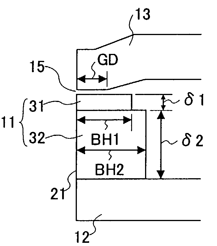
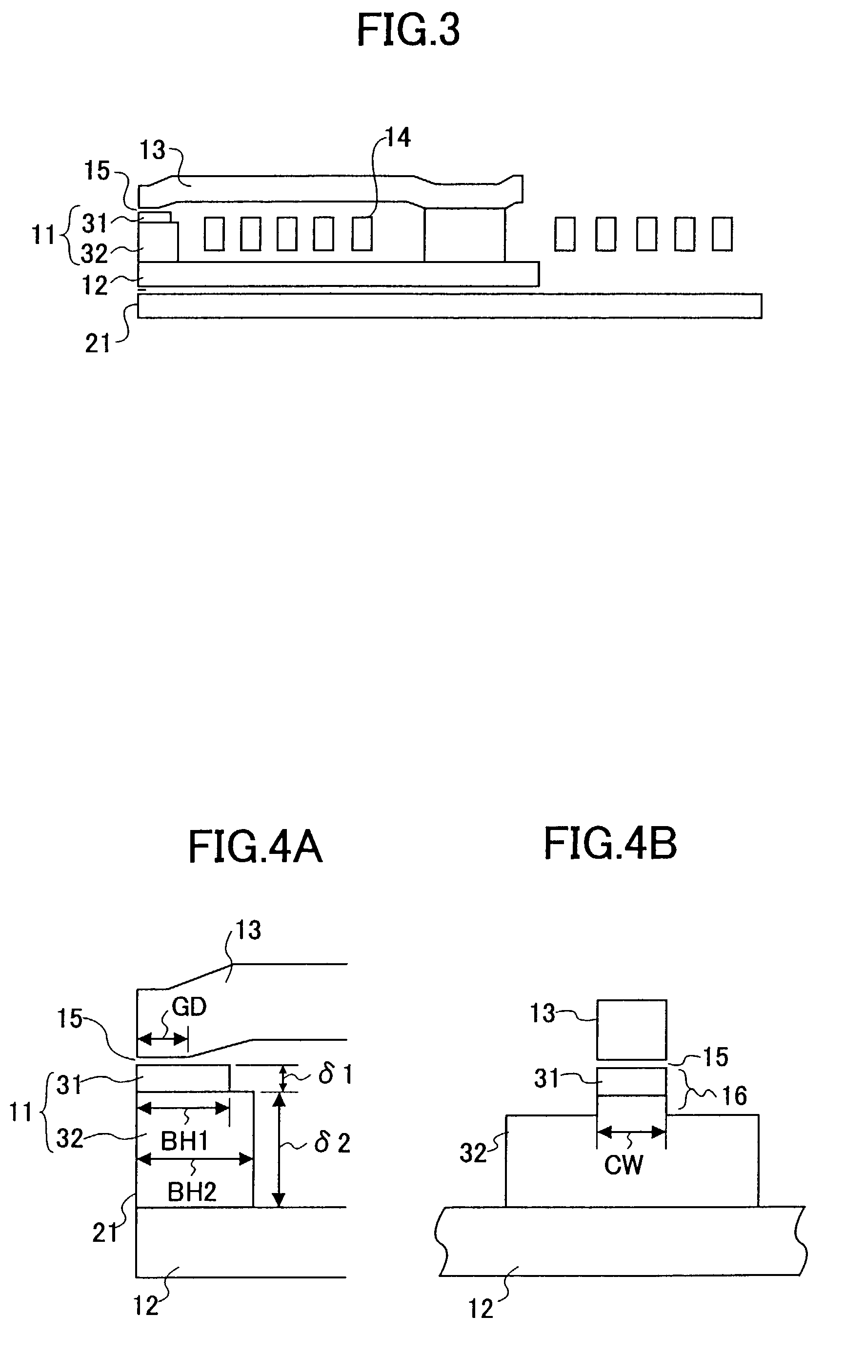
[0013]According to the present invention, a surface perpendicular to the film thickness of the lower sub magnetic pole narrows in the direction from the lower magnetic pole layer towards the upper magnetic pole layer. Since the magnetic flux density is inversely proportional to the area of the surface perpendicular to the magnetic flux direction of the part where the magnetic flux of the magnetic flux density passes, the magnetic flux density of the magnetic flux passing through the lower sub magnetic pole decreases as the lower magnetic pole layer gets closer, when seen in a direction from the part of the lower sub magnetic pole located close to the upper magnetic pole layer towards the lower magnetic pole layer. As a result, at the part of the lower sub magnetic pole located distant from the upper magnetic pole layer, magnetic saturation is less likely to occur. On the other hand, if the surface perpendicular to the film thickness of the part of the lower sub magnetic pole close to the upper magnetic pole layer is narrowed, and especially if the length perpendicular to the medium facing face of the upper sub magnetic pole is shortened, the magnetic flux passing through the lower sub magnetic pole can be efficiently concentrated in the vicinity of the medium facing face near the gap layer. Therefore, a recording magnetic head having a large recording magnetic field and a small recording blur can be achieved.
[0015]According to the magnetic storage device of the present invention, by virtue of the recording magnetic head of a small recording blur and a large recording magnetic field, a magnetic storage device capable of increasing the surface recording density is achieved.

Problems solved by technology

However, with just this method, the surface area through which the magnetic flux of the lower sub magnetic pole may pass is decreased causing the magnetic flux density of such magnetic flux to increase.

Method used


Image

  • Recording magnetic head and magnetic storage device using the same
  • Recording magnetic head and magnetic storage device using the same
  • Recording magnetic head and magnetic storage device using the same

Examples


Embodiment Construction

[0031]The embodiments of the present invention will be explained hereinafter based on the figures.

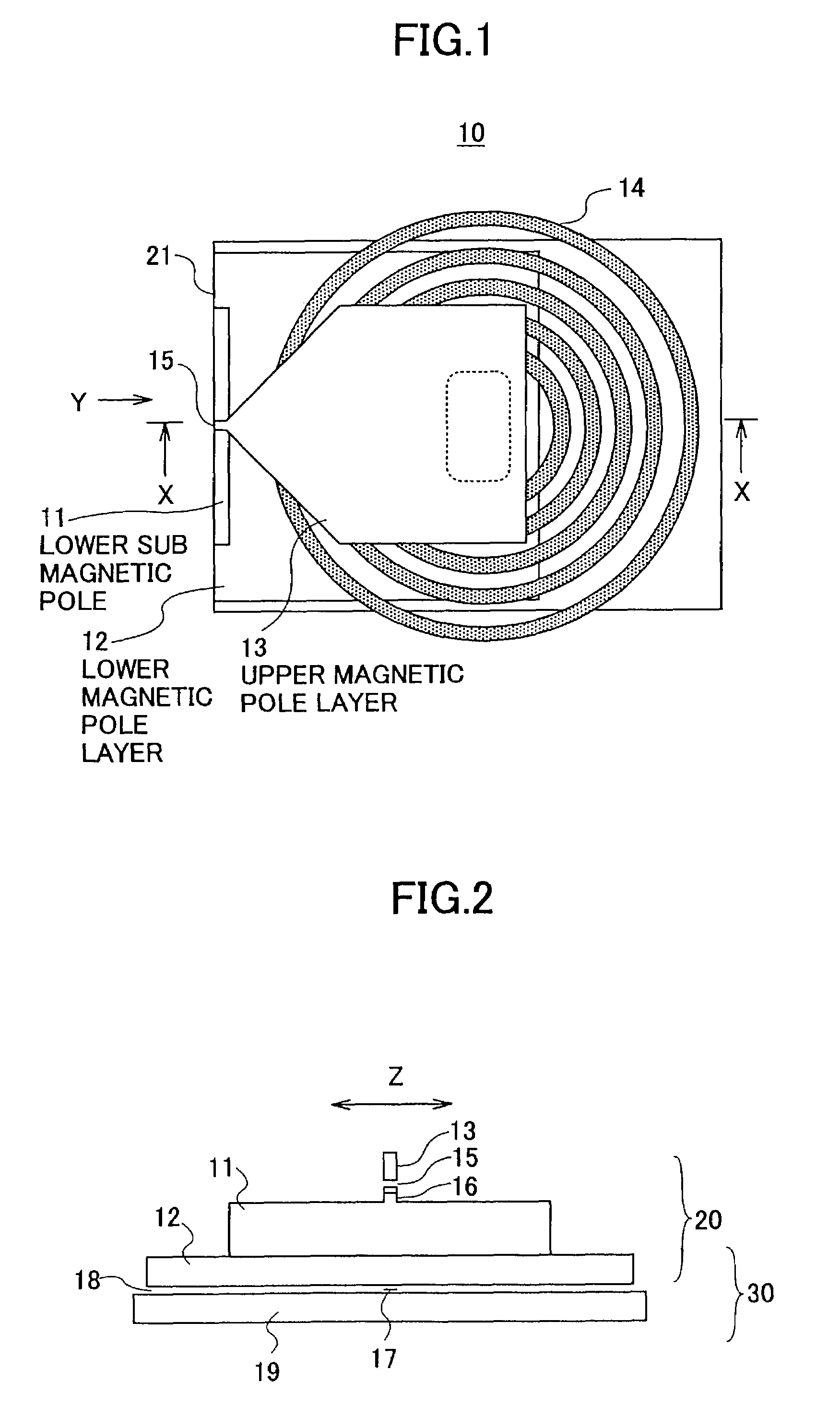
[0032]With reference to FIG. 1 and FIG. 2, a structure of a combined type magnetic head 10 in which a recording magnetic head is provided with a reproducing MR head is described as an example of the recording magnetic head of the present invention. FIG. 1 shows a planar structure of the combined type magnetic head 10 seen from the side of an upper magnetic pole layer of the recording magnetic head 20. FIG. 2 shows a structure of a medium facing face 21 seen from the direction Y represented with an arrow in FIG. 1.

[0033]In the magnetic storage device, recording and reproducing is performed by placing the medium facing face 21 of the combined type magnetic head 10 in close proximity to the magnetic storage medium so as to face each other. Furthermore, the magnetic recording medium moves in a direction from the inside of the plane of the diagram towards the outside of the diagram, or towar...


PUM


Abstract

According to the present invention, a recording magnetic head suitable for increasing a surface recording density and having a large recording magnetic field and a small recording blur is provided. A lower magnetic pole layer and an upper magnetic pole layer opposing the lower magnetic pole layer are formed, and a lower sub magnetic pole composed of a plurality of magnetic layers is formed along a medium facing face on the lower magnetic pole layer. The lengths in a direction perpendicular to the medium facing face of the respective magnetic layers forming the lower sub magnetic pole are longer as the respective magnetic layers get further away from the upper magnetic pole layer.

Description

BACKGROUND OF THE INVENTION[0001]This application claims the benefit of Japanese Patent Application No. 2002-074734 filed Mar. 18, 2002 in the Japanese Patent Office, the disclosure of which is hereby incorporated by reference.[0002]1. Field of the Invention[0003]The present invention generally relates to a recording magnetic head used in a magnetic disk, a magnetic tape and the like, and a magnetic storage device using the same.[0004]2. Description of the Related Art[0005]In a magnetic storage device where information on a magnetic storage medium is recorded and reproduced, a head of a combined type is generally used. The combined type head is a head in which a magnetic head for reproducing using an MR element and the like is provided with a magnetic head for recording of an induction type made from a thin film.[0006]In the magnetic storage device, an approach has been made with regards to the recording magnetic head to narrow the recording track width to increase the surface recor...

Claims


Application Information

Patent Timeline
IPC IPC(8): G11B5/147G11B5/31
CPCG11B5/3116G11B5/3146G11B5/313G11B5/31
Inventor KUTSUZAWA, TOMOKOTAGAWA, IKUYA
Owner FUJITSU LTD
Learn More