Magnetic recording medium and production method therefor
a magnetic recording and production method technology, applied in the field of high-density magnetic recording technology, to achieve the effect of inhibiting the degraded magnetism of a recording region, reducing side cross talk, and improving tracking accuracy
- Summary
- Abstract
- Description
- Claims
- Application Information
AI Technical Summary
Benefits of technology
Problems solved by technology
Method used
Image
Examples
example 1
[0058] A first embodiment according to the present invention will be described.
(1) Step of Preparing Structure Having Magnetic Material of Columnar Structure Separated by Non-magnetic Material
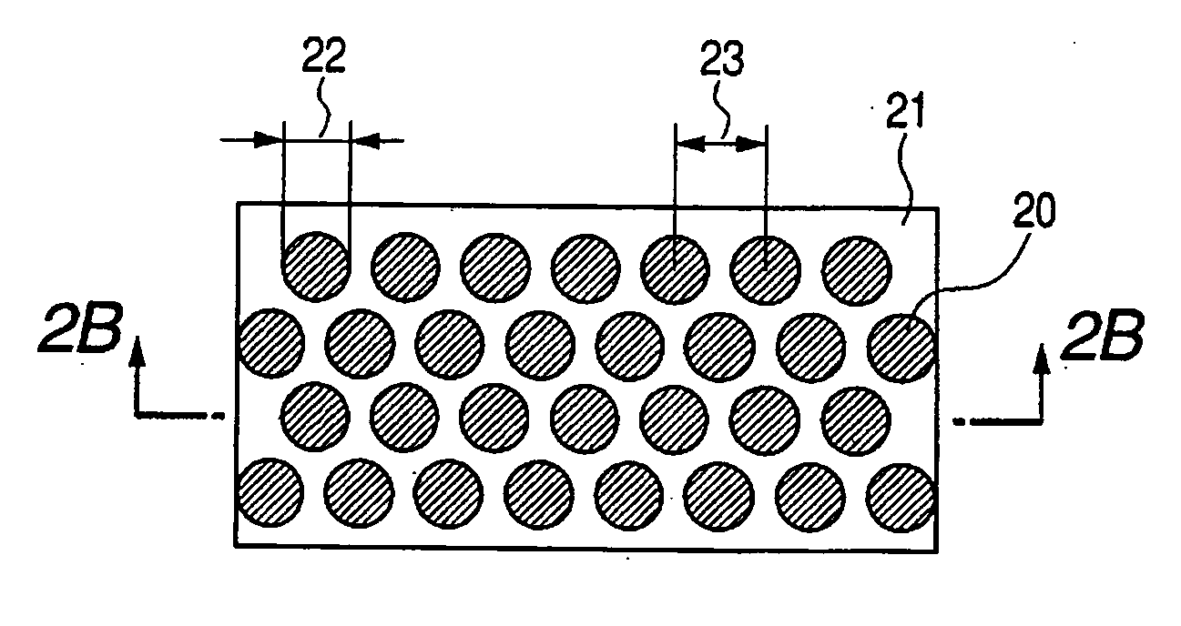
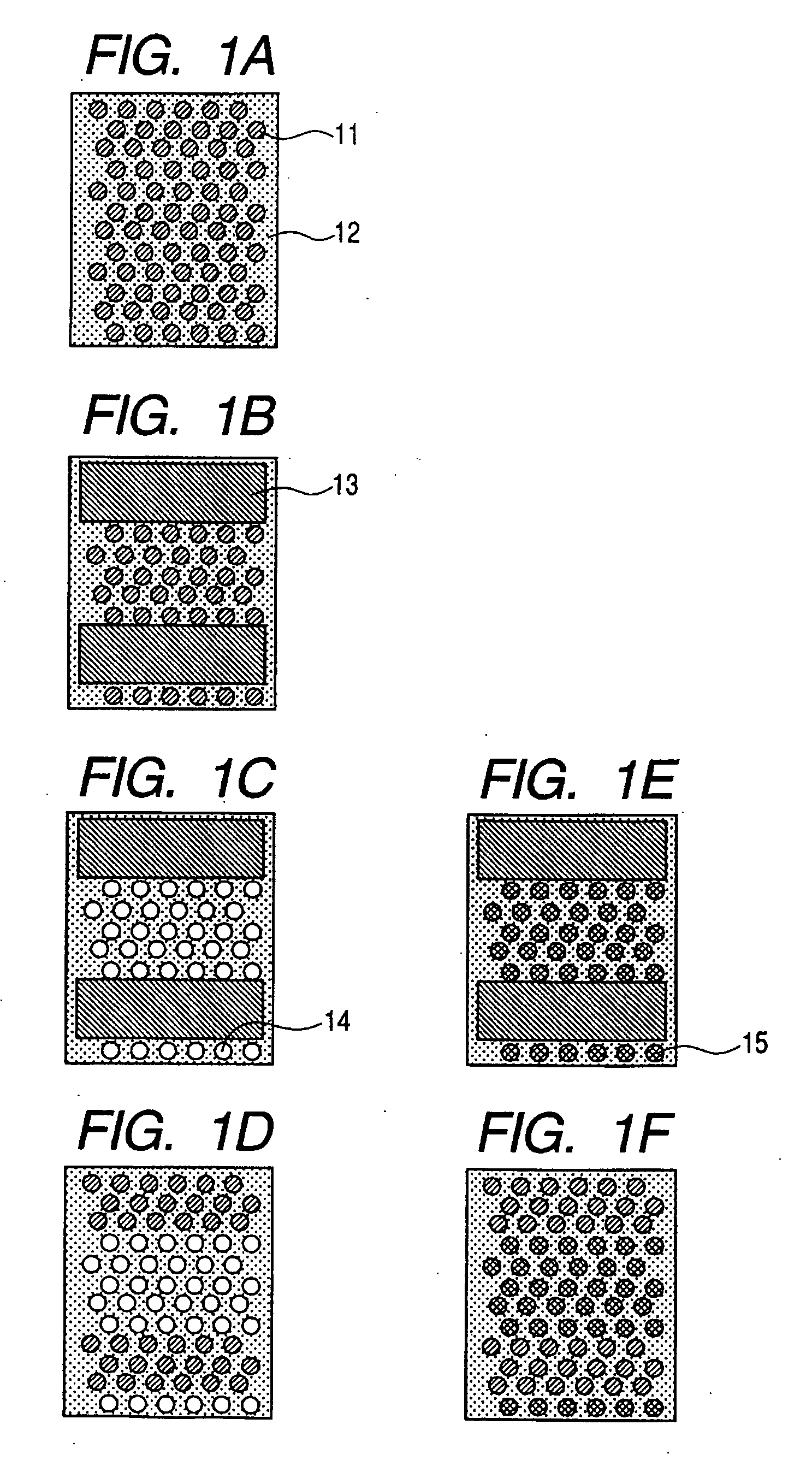
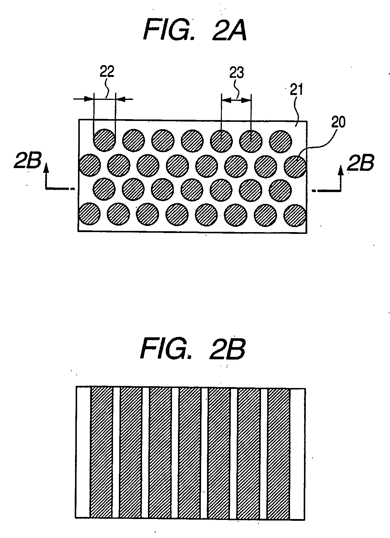
[0059] A backing soft magnetic layer, an intermediate layer and the like were formed on a substrate, and a recording layer formed of a CoCrPt—SiO2 layer with a thickness of 20 nm was formed, in which a magnetic material CoCrPt was separated by a non-magnetic material SiO2. Here, Ru was used for the intermediate layer. The CoCrPt—SiO2 layer was formed by simultaneously sputtering a CoCrPt magnetic target and a SiO2 non-magnetic target in a magnetron sputtering apparatus. As a result of having analyzed the chemical composition, it was confirmed that CoCrPt in a magnetic portion was (Co90Cr10)75Pt25 and Sio2 was 11% by a ratio to CoCrPt. As a result of having observed the surface and the cross section of the above described recording layer made of the above described CoCrPt—SiO2 with a TEM, it ...
example 2
[0067] A second embodiment according to the present invention will be described.
[0068] In the present embodiment, steps (1) and (2) are the same as in Example 1.
(3) Step of Removing Magnetic Material in Region in which Mask is Not Formed or Transforming Magnetic Property
[0069] A magnetic material in a portion which was not covered with a mask was removed, by preparing an etching solution (C) which contains hydrogen peroxide water added to an aqueous solution of H2SO4 having a pH of 1.5, and alternately immersing samples which has passed through the above described steps (1) and (2), into the etching solutions (B) and (C) . It is possible to remove one part or all parts of the magnetic material by controlling an etching period of time.
[0070] A resist was removed, and then the surface structure of the sample was observed with an electron microscope. As a result, it was clear that the magnetic material of the portion which was not covered with the mask was removed, while the magne...
example 3
[0071] A third embodiment according to the present invention will be described.
[0072] In the present embodiment, steps (1) and (2) are the same as in Example 1.
(3) Step of Removing Magnetic Material in Region in which Mask is Not Formed or Transforming Magnetic Property
[0073] An aqueous solution of H2SO4 (D) having a pH of 1.5 was prepared. Samples which have passed through steps (1) and (2) were electrolyzed in an aqueous solution (D) of an electrolyte so that the samples could become an anode. A magnetic material in a portion which was not covered with a mask was removed, by repeating the electrolytic etching step and a step of immersing the sample into an etching solution (B). It is possible to remove one part or the all parts of the magnetic material by controlling an etching period of time.
[0074] A resist was removed, and then the surface structure of the sample was observed with an electron microscope. As a result, it was clear that the magnetic material of the portion wh...
PUM
| Property | Measurement | Unit |
|---|---|---|
| diameter | aaaaa | aaaaa |
| diameter | aaaaa | aaaaa |
| diameter | aaaaa | aaaaa |
Abstract
Description
Claims
Application Information
 - R&D
- Intellectual Property
- Life Sciences
- Materials
- Tech Scout
- Unparalleled Data Quality
- Higher Quality Content
- 60% Fewer Hallucinations
Browse by: Latest US Patents, China's latest patents, Technical Efficacy Thesaurus, Application Domain, Technology Topic, Popular Technical Reports.
© 2025 PatSnap. All rights reserved.Legal|Privacy policy|Modern Slavery Act Transparency Statement|Sitemap|About US| Contact US: help@patsnap.com


