Method of manufacturing combination type thin film magnetic head

Inactive Publication Date: 2006-11-07
HEADWAY TECH INC +1
View PDF14 Cites 3 Cited by
  • Summary
  • Abstract
  • Description
  • Claims
  • Application Information

AI Technical Summary

Benefits of technology

[0023]The present invention has for its object to provide a thin film magnetic head, in which the above mentioned various problems of the conventional combination type thin film magnetic head

Problems solved by technology

However, upon decreasing a track width by utilizing the semiconductor manufacturing process, there is a problem that a sufficiently large magnetic flux could not be obtained due to a miniaturized structure of the pole portion.
Therefore, it is quite difficult to form the pattern of submicron order precisely.
However, these magnetic materials could not be easily formed by sputtering into a film having a given pattern.
However, etching rate is too slow and a track width of submicron order could not be controlled preci

Method used


Image

  • Method of manufacturing combination type thin film magnetic head
  • Method of manufacturing combination type thin film magnetic head
  • Method of manufacturing combination type thin film magnetic head

Examples


Embodiment Construction

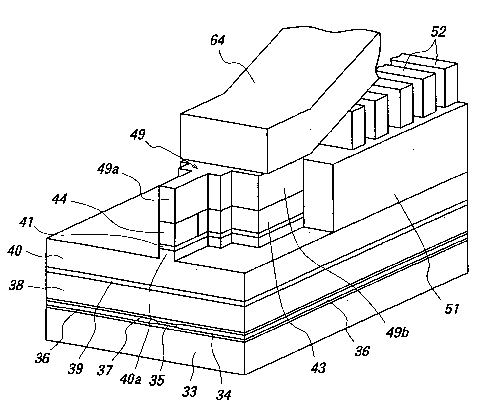
[0066]FIGS. 7–11 are cross sectional views showing successive steps of the method of manufacturing a first embodiment of the combination type thin film magnetic head according to the invention. It should be noted that the structure of a reading GMR head element formed by a magnetoresistive type thin film magnetic head and the method of manufacturing the same are substantially identical with those of the known head. As illustrated in FIG. 7A, an insulating film 32 made of alumina and having a thickness of about 3 μm is deposited on one surface of a substrate 31 made of AlTiC. Furthermore, a bottom shield film 33 made of permalloy for the magnetoresistive type thin film magnetic head is formed on the insulating film with a thickness of about 2–3 μm into a desired pattern by means of a plating method using a photoresist mask.

[0067]Subsequently, after forming an alumina film on the bottom shield film 33 with a thickness of 3–4 μm, a surface is flattened by CMP. Next, after forming a bot...


PUM

PropertyMeasurementUnit
Temperatureaaaaaaaaaa
Angleaaaaaaaaaa

Abstract

On a surface of a bottom pole, a write gap film and first magnetic material film having a high saturation magnetic flux density are formed, and the first magnetic material film is etched to remain a portion extending from an air bearing surface to a throat height zero reference position and a first non-magnetic film is formed in a removed portion. The first non-magnetic material film is polished to obtain a flat surface which is coplanar with a surface of the first magnetic material film. A second magnetic material film having a high saturation magnetic flux density is formed on the flat surface. The second magnetic material film, first magnetic material film, write gap film and bottom pole are partially removed by RIE using a mask formed on the flat surface.

Description

[0001]This is a Divisional of application Ser. No. 10 / 068,877 filed Feb. 11, 2002 now U.S. Pat. No. 6,762,911. The entire disclosure of the prior application is hereby incorporated by reference herein in its entirety.BACKGROUND OF THE INVENTION[0002]1. Field of the Invention[0003]The present invention relates to a combination type thin film magnetic head having an inductive type thin film magnetic head element serving as a writing magnetic converting element and a magnetoresistive type thin film magnetic head element serving as a reading magnetic converting element stacked one on the other, and a method of manufacturing the same. More particularly, the present invention relates to an inductive type writing thin film magnetic head having a narrow record track for attaining a high surface recording density on a magnetic record medium by utilizing magnetic materials having a high saturation magnetic flux density, and a method of manufacturing the same.[0004]2. Description of the Relate...

Claims


Application Information

Patent Timeline
IPC IPC(8): G11B5/127H04R31/00G11B5/31G11B5/39
CPCG11B5/3163G11B5/3967G11B5/3116G11B5/313G11B5/3166Y10T29/49046Y10T29/49043Y10T29/49052Y10T29/49041Y10T29/49044Y10T29/49048
Inventor SASAKI, YOSHITAKAKAMIGAMA, TAKEHIRO
Owner HEADWAY TECH INC
Why Eureka
Try Eureka