Current sensor

Inactive Publication Date: 2009-10-22
MITSUBISHI ELECTRIC CORP
View PDF0 Cites 8 Cited by
  • Summary
  • Abstract
  • Description
  • Claims
  • Application Information

AI Technical Summary

Benefits of technology

[0021]In the current sensor according to one aspect of the present invention, the core includes the magnetic material portion and the non-magnetic material portion, and the core is divided into a lot of parts in the circumferential direction of the core by the magnetic material portion and the non-magnetic material portion. In the configuration of the current sensor according to the aspect of the present invention, the non-magnetic material portion has the remarkably large magnetic resistance, so that the magnetic flux passing through the core can be decreased to suppress the magnetic flux saturation in the core. Accordingly, the provision of the feedback circuit is eliminated, and higher current than the conventional art can be measured with the core having the same size as conventional one. Conversely, the high current can be measured with the core smaller than conventional one.
[0022]On the other hand, when the core is simply divided without any conditions, the leakage flux is generated from the cross section at the divided portion to lose the evenness of the magnetic flux density in the whole circumference of the core

Problems solved by technology

However, even if the high current is measured with the current sensor, sometimes the current is not correctly measured because a magnetic flux generated in the core is saturated.
Conventionally, when the high current is measured with the conventional current sensor, it is necessary tha

Method used


Image

  • Current sensor
  • Current sensor
  • Current sensor

Examples


first embodiment

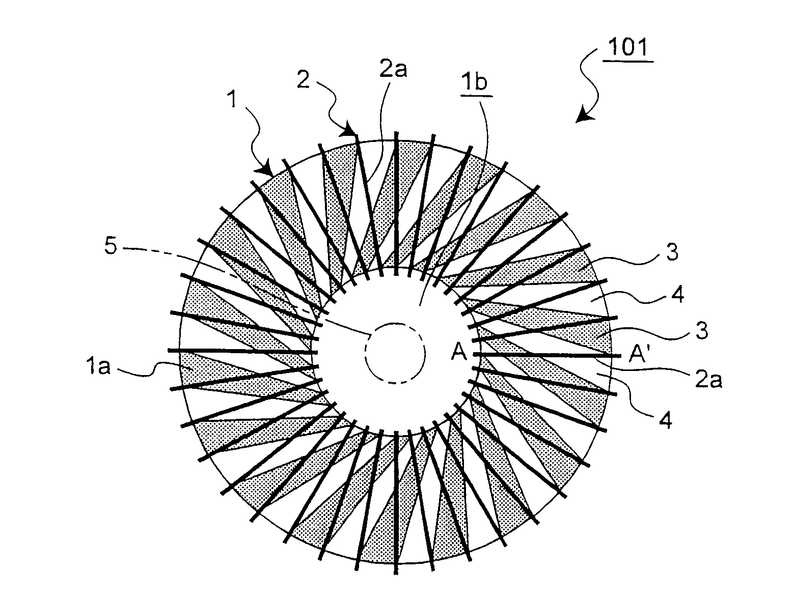
[0047]A current sensor 101 according to a first embodiment of the present invention will be described with reference to FIGS. 1 to 3, 4A, and 4B. As shown in FIG. 1, the current sensor 101 includes a core 1 and a secondary winding 2.

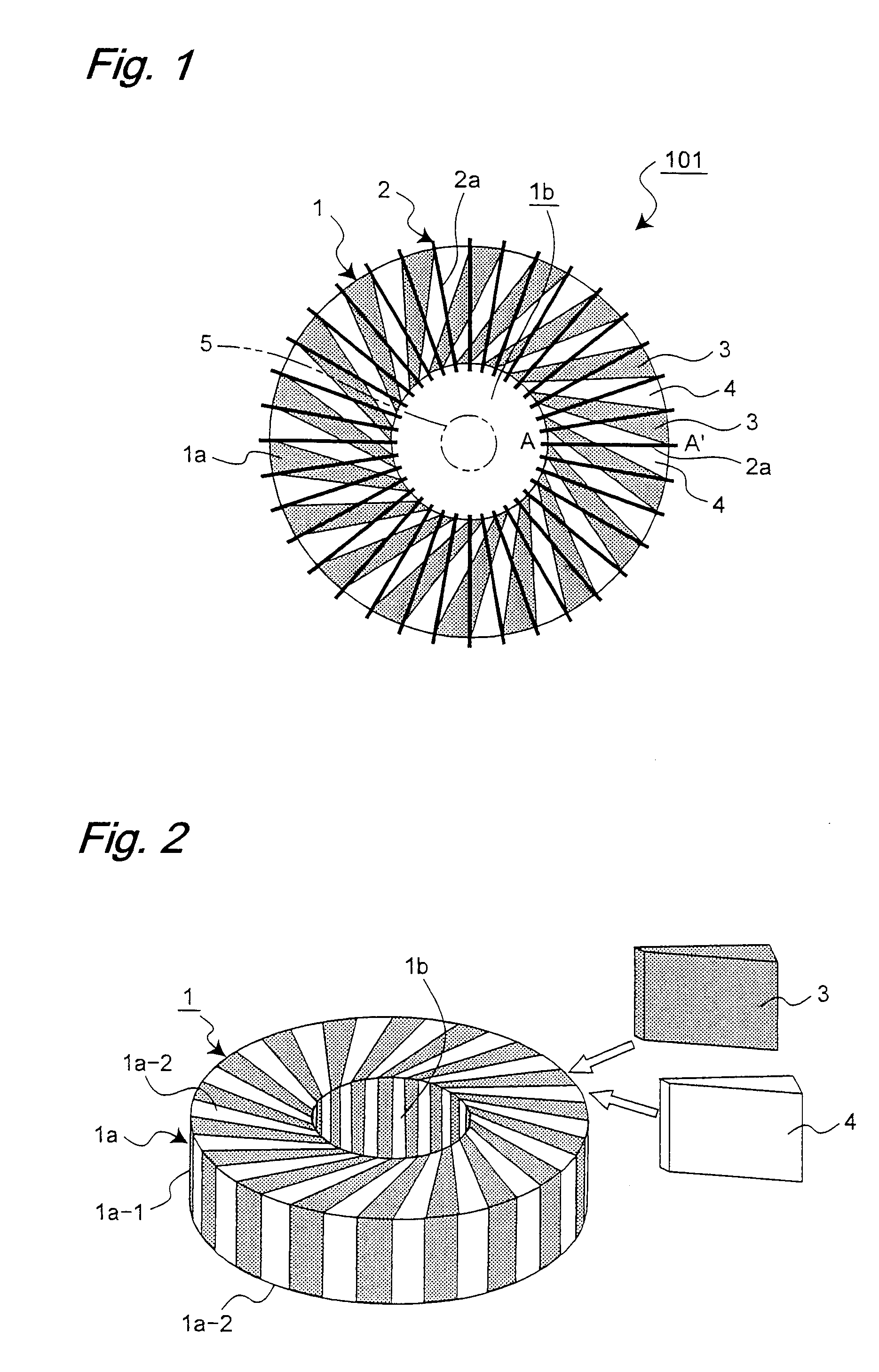
[0048]The core 1 has a body portion 1a and a through-hole. The body portion 1a is formed into an annular shape like a pipe ring. The through-hole is made in a central portion 1b of the current sensor 101. The body portion 1a includes a circumferential surface 1a-1 and upper and lower surfaces 1a-2. In the first embodiment, the upper and lower surfaces 1a-2 are formed by flat surfaces respectively. Alternatively the upper and lower surfaces 1a-2 may be formed into a projected shape such as a semicircular shape and the like. A primary conductor 5 for passing the primary current which corresponds to a current to be measured is disposed along the central portion 1b, namely, the primary conductor 5 is disposed while penetrating through the core 1.

[0049]The co...

second embodiment

[0067]A current sensor 106 according to a second embodiment of the present invention will be described below with reference to FIG. 10. In FIG. 10, only a core portion constituting the current sensor 106 is shown while the secondary winding 2 is omitted.

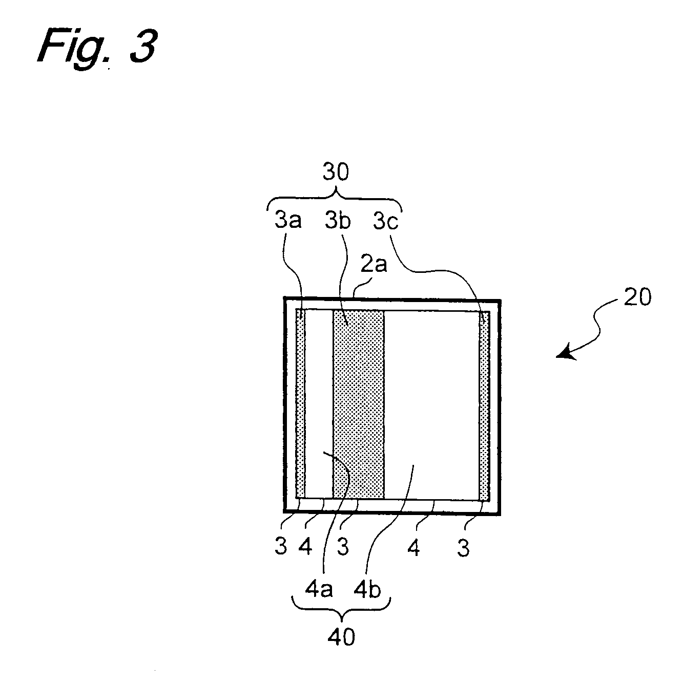
[0068]In the first embodiment mentioned above, the core 1 is formed by the one structure in which the magnetic material portion 3 and the non-magnetic material portion 4 are integrally formed. On the other hand, in the current sensor 106 of the second embodiment, a core 1 includes plural (two in the second embodiment) divided cores 21 and 22. The second embodiment differs from the first embodiment in this point. The plural divided cores are combined to form the one core 1, which allows a distribution having any sensitivity coefficient to be obtained as a current sensor characteristic.

[0069]Regarding other configurations and modifications of the current sensor 106, since the explanation for the first embodiment mentioned above can be ...

third embodiment

[0089]A current sensor according to a third embodiment of the present invention will be described with reference to FIGS. 14 and 15. In the current sensor of the third embodiment, the current sensors of the first or second embodiment are produced by plating or a printed board having good shape controllability.

[0090]FIGS. 14 and 15 shows a current sensor 107 of the third embodiment in which the configuration of the current sensor 101 of FIG. 1 is produced with the board. Obviously the configurations of the current sensors 102 to 106 may be produced in the below-mentioned manner.

[0091]The current sensor 107 includes a first winding pattern board 9-1, a second winding pattern board 9-2, and a core pattern board 12 sandwiched between the winding pattern boards 9-1 and 9-2. In the first winding pattern board 9-1, a first conductor 8a is formed radially by the patterning on the board, such as the printed board, which is made of the non-magnetic material. The first conductor 8a is a conduc...


PUM


Abstract

A core is divided by alternately arranging plural magnetic material portions and plural non-magnetic material portions in a circumferential direction of the core through which a primary conductor penetrates. A conductor is wound around the core under conditions in which each core cross section of the core intersects the magnetic material portion and the non-magnetic material portion, each core cross section including a cut end surface of each conductor of a secondary winding wound around the core, and a ratio of a magnetic material portion cross-sectional area of the magnetic material portion to a non-magnetic material portion cross-sectional area of the non-magnetic material portion at the core cross section is kept constant at each core cross section.

Description

BACKGROUND OF THE INVENTION[0001]1. Field of the Invention[0002]The present invention relates to a current sensor which measures a current passed through a primary conductor.[0003]2. Description of the Related Art[0004]When a high current is measured, because the direct passage of the high current through an ammeter is dangerous, a current sensor is used to measure the high current. In the current sensor, a primary current is decreased and supplied to a secondary side with a current transformer (CT), thereby measuring a secondary current. The current transformer is formed by utilizing an alternating-current characteristic, and the current transformer has a structure in which the secondary current is taken out from a coil formed by winding a conductor around a core (iron core).[0005]However, even if the high current is measured with the current sensor, sometimes the current is not correctly measured because a magnetic flux generated in the core is saturated. Therefore, in order to su...

Claims


Application Information

Patent Timeline
IPC IPC(8): G01R19/00
CPCH01F3/10H01F3/14H01F17/0033H01F27/346H01F30/16H01F38/30H01F2027/2814
Inventor NISHIURA, RYUICHIMAKITA, YONISHIZAWA, HIROSHIYOSHIDA, TADAHIROKIM, TAE HYUN
Owner MITSUBISHI ELECTRIC CORP
Why Eureka
Try Eureka