Eureka AIR delivers breakthrough ideas for toughest innovation challenges, trusted by R&D personnel around the world.

High-voltage bus induction power taking device and method

A technology of inductive power acquisition and high-voltage bus, which is applied in the direction of circuit devices, battery circuit devices, emergency protection circuit devices, etc., can solve the problems of saturation heating, affecting practicability, unfavorable installation of fully enclosed ring structure, etc., to achieve suppression of saturation, easy to install effects

Pending Publication Date: 2020-04-17
唐山东唐电气股份有限公司
View PDF8 Cites 6 Cited by
  • Summary
  • Abstract
  • Description
  • Claims
  • Application Information

AI Technical Summary

Problems solved by technology

Most of these schemes use a special current transformer (CT) as a self-excited power supply. These methods have the following disadvantages: due to the closed core, when the current is too large, it is easy to cause saturation heating, and the current in the wire changes, so the magnetic field changes. The energy processing method is unreasonable, and generally it will be released as heat energy, which will affect the surrounding environment; at the same time, the fully enclosed ring structure is not conducive to installation. For example, it is impossible to install equipment on the completed bus, which affects the practicability

Method used


Image

  • High-voltage bus induction power taking device and method
  • High-voltage bus induction power taking device and method
  • High-voltage bus induction power taking device and method

Examples


Embodiment 1

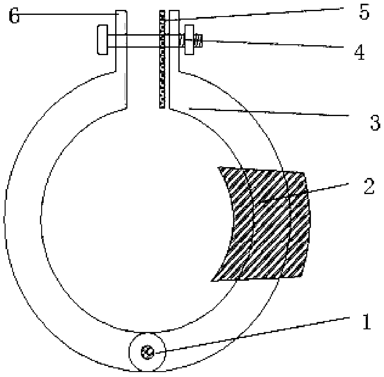
[0022] Embodiment 1: as Figure 1 to Figure 5 As shown, a high-voltage bus induction power-taking device and method, including an induction power-taking device and a power processing device; it is characterized in that the induction power-taking device is composed of two C-shaped magnetic cores, and the bottom of the two C-shaped magnetic cores Connected by the rotating shaft, there are protrusions on the upper part of the two C-shaped magnetic cores, and there is a hole in the middle of the protrusions, and the fastening bolts pass through the holes to fix the magnetic cores. There is a coil wound in the middle of either side of the C-shaped magnetic core; when installing, the interface can be opened, inserted into the busbar, and then fastened to the busbar by bolts.

[0023] The power processing device is composed of a filter circuit, a rectifier circuit, a low-pass filter circuit, an intelligent energy discharge module, a voltage stabilizing circuit, a lithium battery char...


PUM


Abstract

The invention discloses a high-voltage bus induction power taking device and method. The high-voltage bus induction power taking device comprises an induction power taking device and an electric energy processing device. The induction power taking device is composed of two C-shaped magnetic cores, the bottoms of the two C-shaped magnetic cores are connected through a rotating shaft, protrusions are arranged on upper portions of the two C-shaped magnetic cores, holes are formed in the middles of the protrusions, fastening bolts penetrate through the holes to fix the magnetic cores, heat-resisting rubber pads are arranged at the protrusions, the magnetic cores are not completely closed, and coils are wound in the middles of any sides of the two C-shaped magnetic cores. The electric energy processing device comprises an intelligent discharge module, the intelligent discharge module adopts a single-chip microcomputer to control the on-off of a field effect transistor, and when the output voltage is higher than a certain limit value, an LED cold light source is lightened to release redundant energy. A double-C-shaped opening and closing structure is easy to install, and the gaps can effectively restrain the saturation of the magnetic cores; for energy change generated by current change, excess energy can be released in time, the cold light source is used for preventing temperature rise, and the stability of the induction coil and the circuit voltage is maintained.

Description

technical field [0001] The invention relates to the technical field of high-voltage bus induction power-taking devices, in particular to an induction power-taking device and method for high-voltage bus in a switch cabinet. Background technique [0002] At present, current-carrying busbars, busbars and other power equipment in substations and switchgears and their nodes will experience excessive temperature rise when the load current is too large or the surface is oxidized. The performance is degraded, leading to breakdown, fault and power outage. Many of the major accidents in general substations are caused by the overheating of the busbar or busbar joints, resulting in equipment damage, power grid outage accidents, and may also cause loss of life and property. By monitoring the operation of the temperature of busbar contacts, high-voltage cable joints, and high-voltage switch contacts, it can effectively prevent the occurrence of high-voltage power transmission and transfo...

Claims


Application Information

Patent Timeline
Patent Type & Authority Applications(China)
IPC IPC(8): H02J50/10H02H9/04H01F27/245H01F38/14H02J7/02H02J7/34
CPCH02J50/10H02H9/045H02H9/047H01F38/14H01F27/245H02J7/345
Inventor 樊爱东吴宝江张致豪
Owner 唐山东唐电气股份有限公司
Why Eureka
Eureka Blog
Learn More