Optical coupling device, method of producing the same, and optical apparatus using the same

Inactive Publication Date: 2003-05-15
SAMSUNG ELECTRONICS CO LTD
View PDF4 Cites 16 Cited by
  • Summary
  • Abstract
  • Description
  • Claims
  • Application Information

AI Technical Summary

Problems solved by technology

However, since only the image is enlarged, the picture quality of the image is poor.
In addition, the dichroic mirror takes a lot of space in a project

Method used


Image

  • Optical coupling device, method of producing the same, and optical apparatus using the same
  • Optical coupling device, method of producing the same, and optical apparatus using the same
  • Optical coupling device, method of producing the same, and optical apparatus using the same

Examples


Embodiment Construction

[0042] Hereinbelow, the present invention will be described in greater detail by referring to the appended drawings.

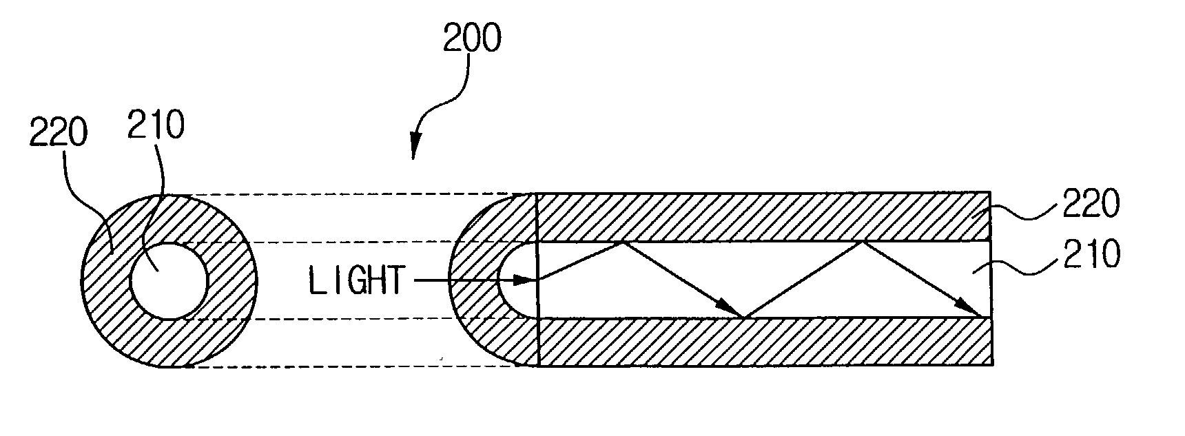
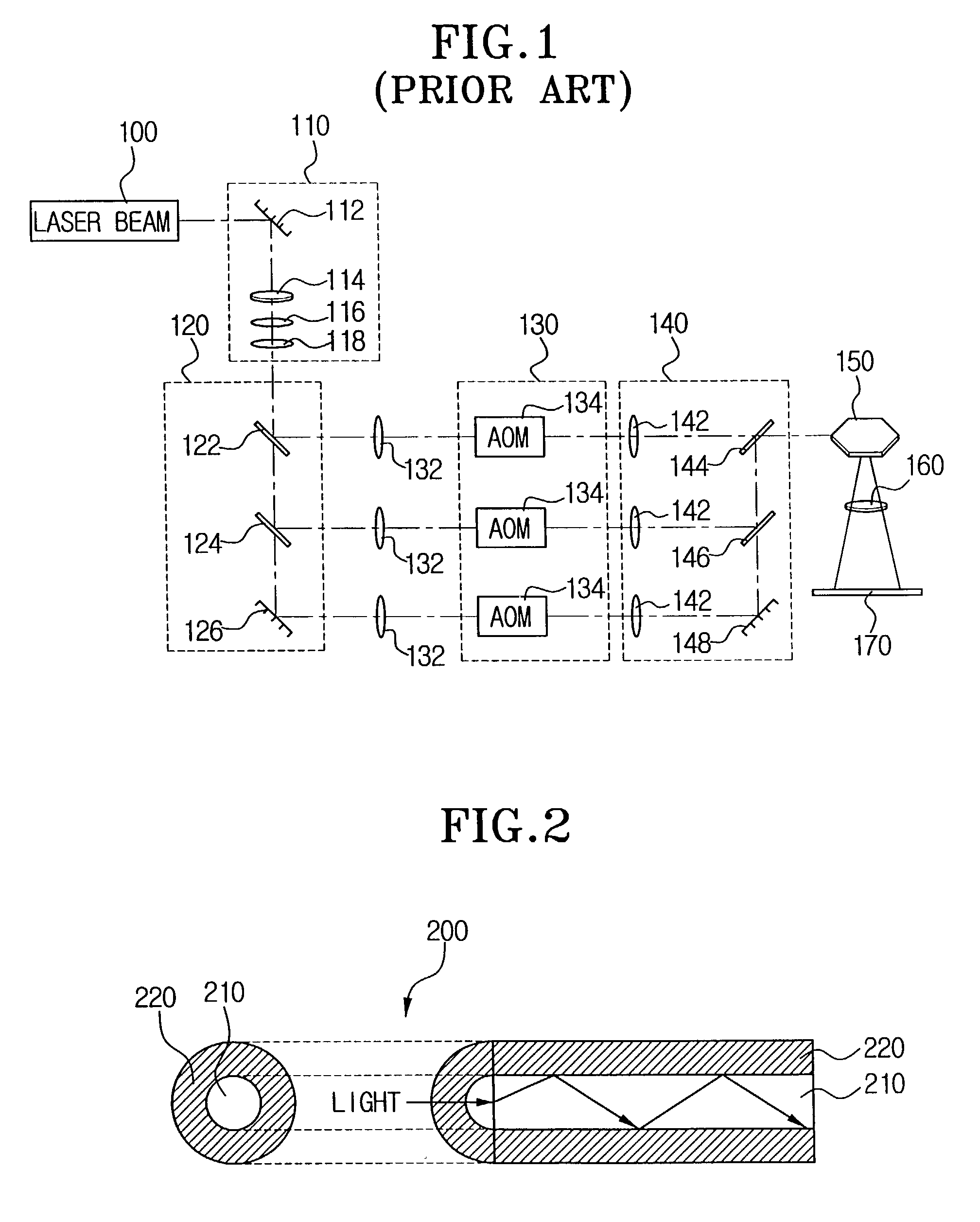
[0043] FIG. 2 is a view showing a basic structure of an optical fiber used in the present invention. Referring to FIG. 2, the optical fiber 200 has a core 210 and a clad 220.

[0044] The optical fiber 200 is a fiber made using a transparent dielectric substance such as quarts glass and plastic. The most widely used is a silicon oxide (SiO.sub.2) optical fiber, which has a thickness of a hair. The refractive index of the clad 220 is less than that of the core 210. Therefore, the light projected to the core 210 passes through the core 210 without any loss of light because the light is repeatedly and totally reflected at the boundary of the core 210 and the clad 220, as shown in FIG. 2.

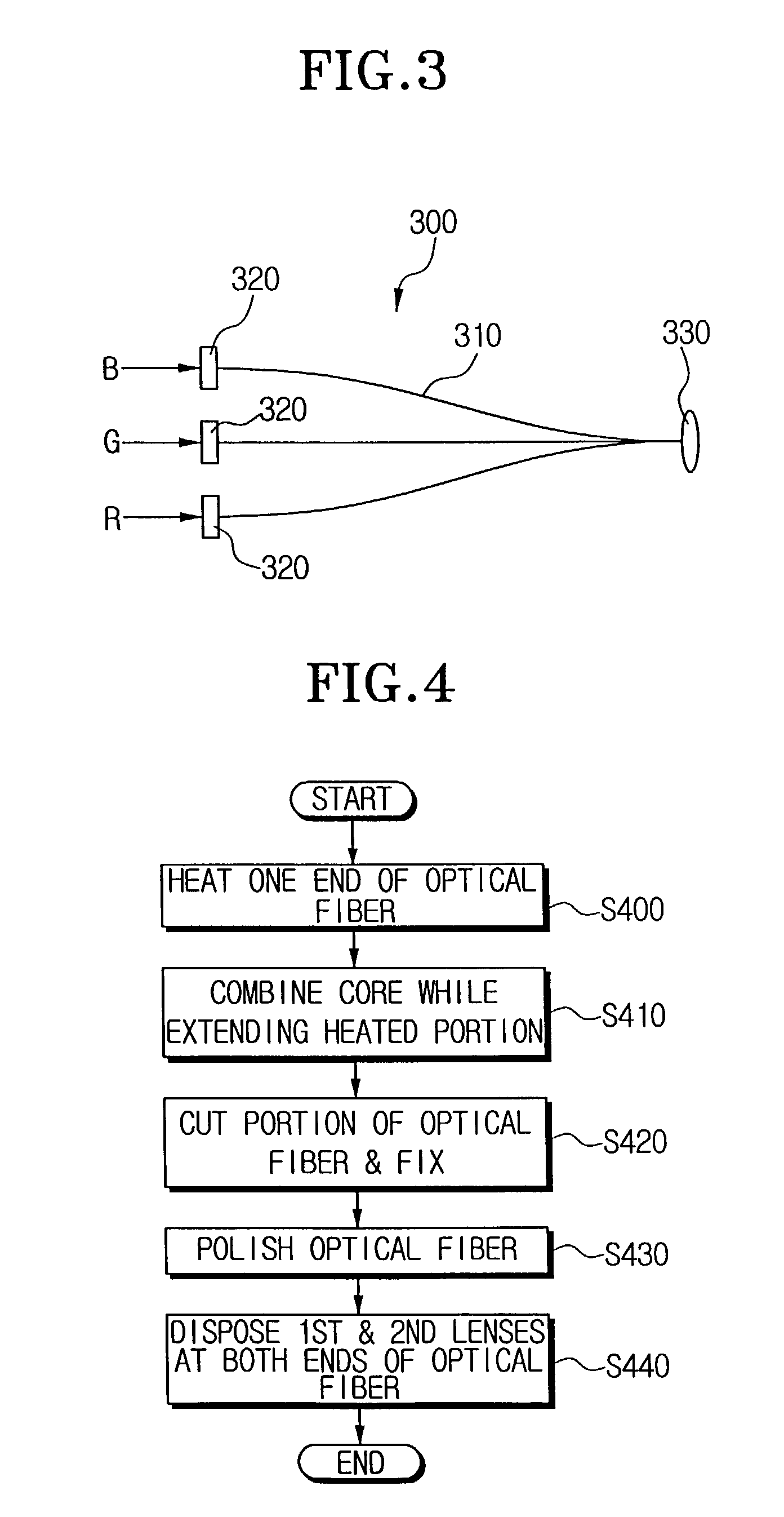
[0045] FIG. 3 is a view showing an optical coupling device using the optical fiber according to the present invention, and FIG. 4 is a flow chart showing a method of producing the optical cou...


PUM


Abstract

An optical coupling device, a method of producing the same, and an optical apparatus using the same. A light transmitting medium of the optical coupling device is made of optical fibers to transmit the light. Three RGB laser beams can be compounded by forming one output end after heating one end of the optical fibers. Input ends of the optical fibers each have a lens to collimate each laser beam. A collimating lens installed at an output end of the optical fibers changes the compounded laser beam to a parallel ray. The optical coupling device made of the optical fibers can be applied to an image reproducing apparatus such as a projector and a projection TV. Especially, when the optical coupling device using the optical fibers is applied to an image reproducing apparatus having a DMD (digital micro-mirror device), the size of the image reproducing apparatus can be reduced and the quality of the image reproduced is improved.

Description

[0001] 1. Field of the Invention[0002] The present invention relates to an optical coupling device, a method of producing an optical coupling device, and an optical apparatus using the same, and, more particularly, to an optical coupling device to form a compound laser beam having RGB information by using optical fiber, a method of producing an optical coupling device, and an optical apparatus using the same.[0003] This application is based on Korean Patent Application No. 2001-69960 filed on Nov. 10, 2001, the disclosure of which is incorporated herein by reference in its entirety.[0004] 2. Description of the Related Art[0005] A projector forms an image by projecting an input image signal onto a screen. The projector is used for a presentation in a meeting room, projection in a cinema, and realization of a home theater. More recently, an LCD (liquid crystal display) is mostly used for a projector, and sometimes a CRT (cathode ray tube) is used.[0006] A flat plate device such as an ...

Claims


Application Information

Patent Timeline
IPC IPC(8): G02B6/28G02B6/00G02B6/42H04N9/31
CPCG02B6/2856H04N9/3129G02B6/4298G02B6/4249G02B6/00
Inventor DHO, SANG-WHOE
Owner SAMSUNG ELECTRONICS CO LTD
Why Eureka
Try Eureka