Device and method for measuring six degrees of freedom

a technology of a device and a measurement method, applied in the direction of angle measurement, using reradiation, instruments, etc., can solve the problems of complicated and expensive implementation, inconvenient user implementation, complicated and expensive implementation

Inactive Publication Date: 2010-05-27
FARO TECH INC
View PDF14 Cites 234 Cited by
  • Summary
  • Abstract
  • Description
  • Claims
  • Application Information

AI Technical Summary

Benefits of technology

[0017]At least an embodiment of a laser tracker system for measuring six degrees of freedom, the system may include a tracking unit comprising and a target. The tracking target may include a payload assembly rotatable around at least one axis. The payload assembly may include a main optics assembly structured to emit a first laser beam and a pattern projector assembly structured to emit a second laser beam shaped into a two-dimensional pattern. The target may include a retroreflector and a position sensor assembly provided proximate to the retroreflector. A center of symmetry of the retroreflector is provided on a different plane than a plane of the position sensor assembly.

Problems solved by technology

These motorized features are complicated and expensive.
In the first instance, the implementation is complicated and expensive and, in the second instance, the implementation is inconvenient for the user.
For this reason, performance tends to degrade in a handheld system.
Such a damped tilt sensor responds sluggishly to changes in roll angle, which is undesirable.
The fourth system, which reflects light directly from a beam splitter to a photosensitive array to view lines on a cube corner, is limited in its depth of field before the line images on the array become blurry and distorted.
This aperture is only moderately accurate in the case of the PSD and relatively slow in the case of the photosensitive array.
All three means, as described above, are complicated and expensive.

Method used


Image

  • Device and method for measuring six degrees of freedom
  • Device and method for measuring six degrees of freedom
  • Device and method for measuring six degrees of freedom

Examples


Embodiment Construction

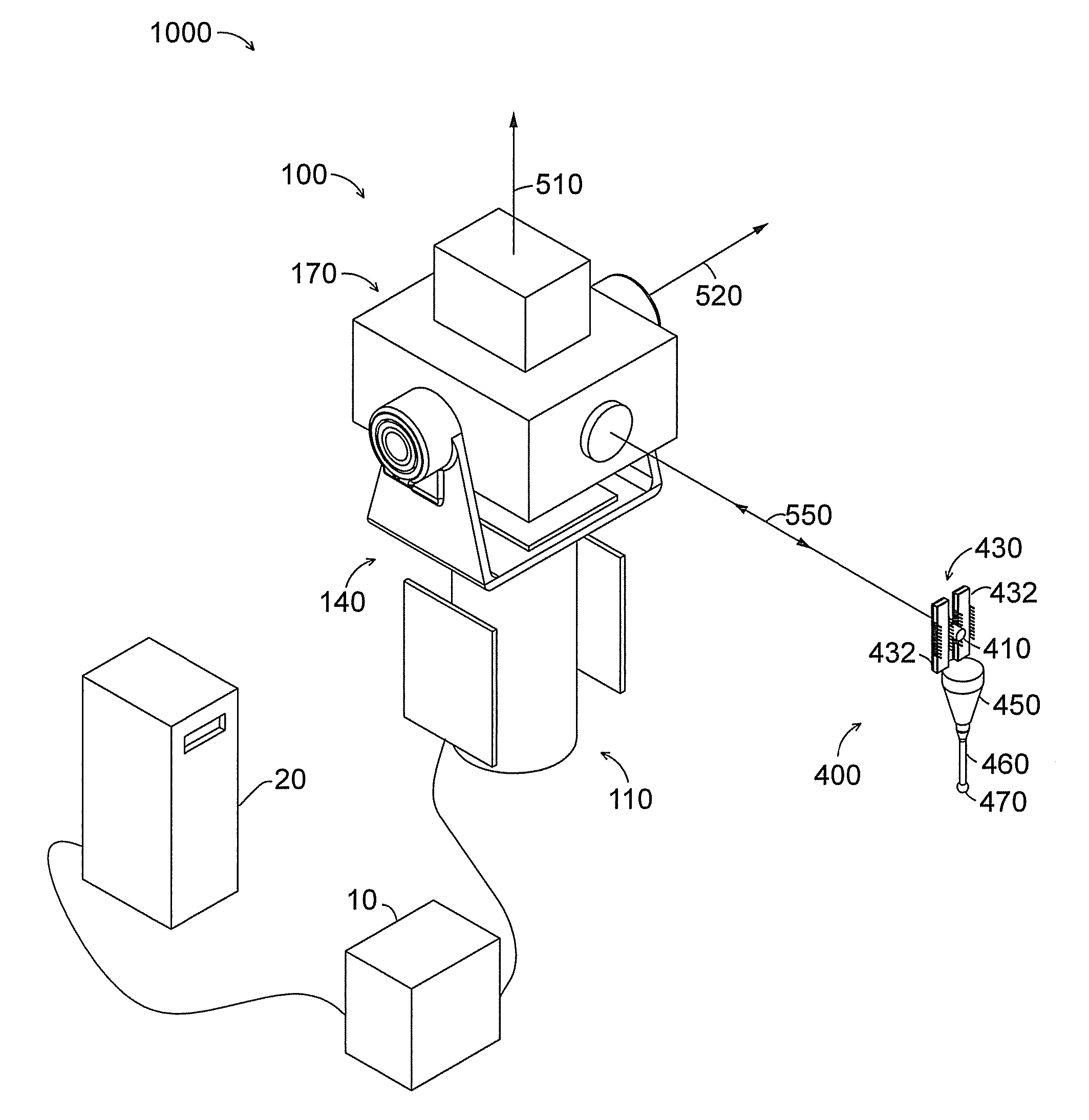
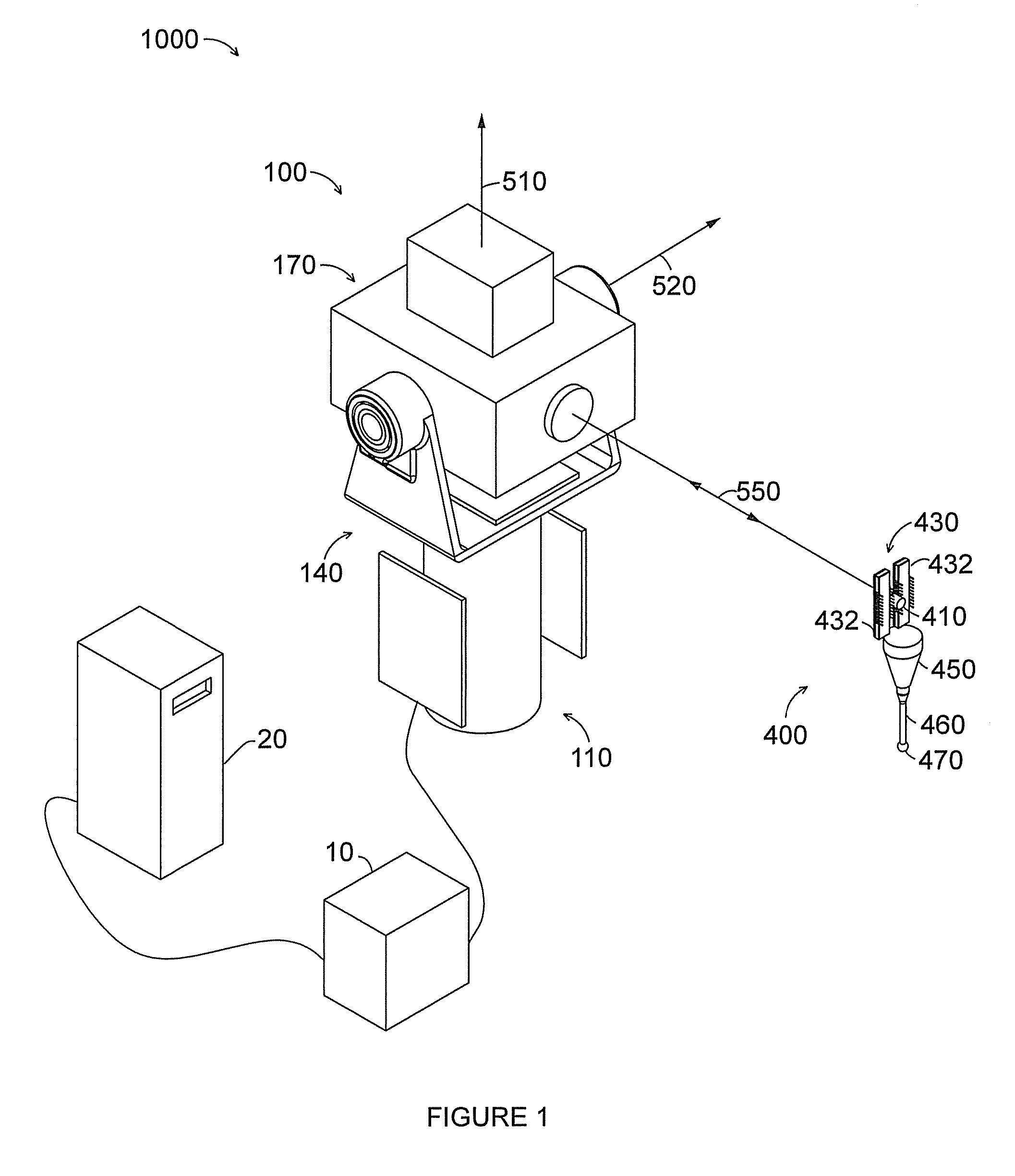
[0039]As shown in FIG. 1, an exemplary six degree of freedom (6 DOF) tracking system 1000 may comprise tracking unit 100, target 400, power supply / control unit 10, and computer 20. Six degrees of freedom may be the x, y, z coordinates, and the pitch, roll, and yaw angles of target 400 for example.

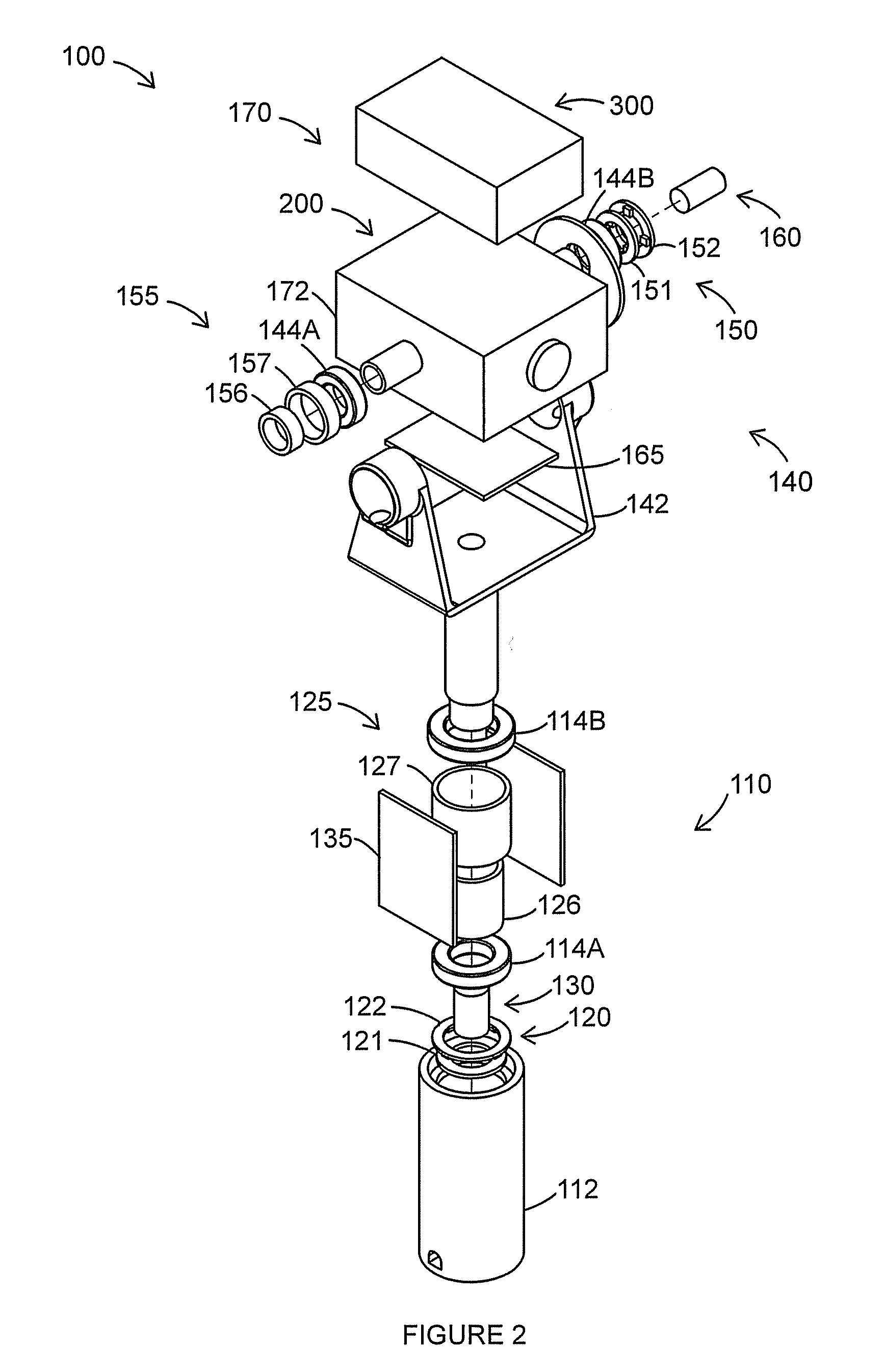
[0040]Tracking unit 100 may comprise azimuth assembly 110, zenith assembly 140, and payload assembly 170. Azimuth assembly 110 is stationary with respect to the stand to which it is mounted. Zenith assembly 140 rotates about azimuth axis 510, and payload assembly 170 rotates about zenith axis 520. In addition, because payload assembly 170 is mounted to zenith assembly 140, it rotates about azimuth axis 510 as well as zenith axis 520.

[0041]Power supply / control unit 10 provides power to tracking unit 100 and may also provide control and computing functions. Computer 20 may use a variety of software packages to analyze and display data.

[0042]Target 400 comprises retroreflector 410, position se...


PUM


Abstract

A laser tracker system for measuring six degrees of freedom may include a main optics assembly structured to emit a first laser beam, a pattern projector assembly structured to emit a second laser beam shaped into a two-dimensional pattern, and a target. The target may include a retroreflector and a position sensor assembly. A center of symmetry of the retroreflector may be provided on a different plane than a plane of the position sensor assembly. A method of measuring orientation of a target may include illuminating the target with a laser beam comprising a two-dimensional pattern, recording a position of the two-dimensional pattern on a position sensor assembly to create a measured signature value of the two-dimensional pattern, and calculating an orientation of the target based on the measured signature value.

Description

CROSS REFERENCE TO RELATED APPLICATIONS[0001]This application claims priority to U.S. Provisional Application No. 61 / 115,136, filed Nov. 11, 2008 the entire contents of each of which are incorporated herein by reference.BACKGROUND[0002]The present disclosure relates to a coordinate measuring device. One set of coordinate measurement devices belongs to a class of instruments that measure the three-dimensional (3D) coordinates of a point by sending a laser beam to the point. The laser beam may impinge directly on the point or may impinge on a retroreflector target that is in contact with the point. In either case, the instrument determines the coordinates of the point by measuring the distance and the two angles to the target. The distance is measured with a distance-measuring device such as an absolute distance meter or an interferometer. The angles are measured with an angle-measuring device such as an angular encoder. A gimbaled beam-steering mechanism within the instrument directs...

Claims


Application Information

Patent Timeline
Patent Type & Authority Applications(United States)
IPC IPC(8): G01B11/14G01B11/26
CPCG01B11/03G01C15/002G01S17/66G01S5/163G01S1/70
Inventor BRIDGES, ROBERT E.BROWN, LAWRENCE B.HOFFER, JR., JOHN M.ACKLEY, KEVIN R.
Owner FARO TECH INC
Why Eureka
Try Eureka