Scanning endoscope

a scanning beam and endoscope technology, applied in the field of scanning beam systems, can solve the problems of limiting the image quality and dynamic range of digital endoscopes and laparoscopes, exhibiting other undesirable artifacts, and limiting the diameter of the endoscope, so as to achieve the effect of achieving high resolution

Inactive Publication Date: 2005-01-27
MICROVISION
View PDF32 Cites 350 Cited by
  • Summary
  • Abstract
  • Description
  • Claims
  • Application Information

AI Technical Summary

Problems solved by technology

Today's digital endoscopes and laparoscopes may suffer from limited image quality and dynamic range and often exhibit other undesirable artifacts.
In the case of distal imaging systems in particular, diameter limitations have been a common hindrance to higher resolution.

Method used


Image

  • Scanning endoscope
  • Scanning endoscope
  • Scanning endoscope

Examples


Embodiment Construction

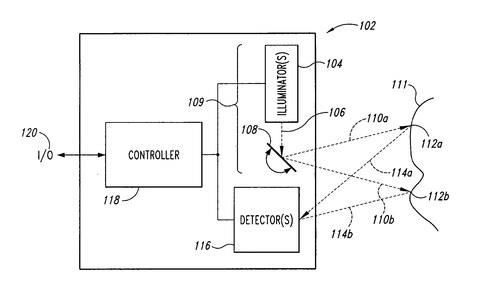
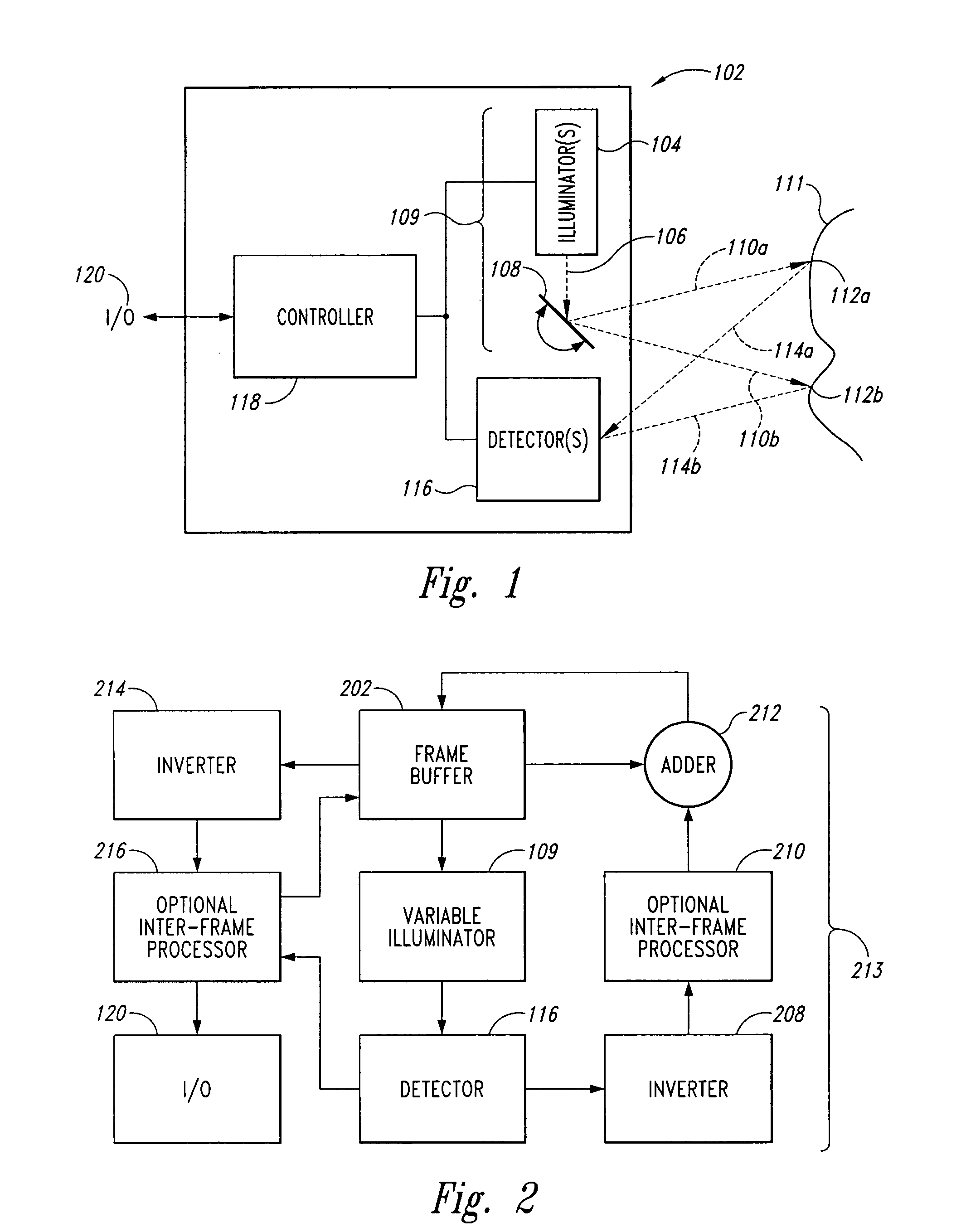
[0057]FIG. 1 shows a block diagram of a scanned beam imager 102. An illuminator 104 creates a first beam of light 106. A scanner 108 deflects the first beam of light across a field-of-view (FOV) to produce a second scanned beam of light 110, shown in two positions 110a and 110b. The scanned beam of light 110 sequentially illuminates spots 112 in the FOV, shown as positions 112a and 112b, corresponding to beam positions 110a and 110b, respectively. While the beam 110 illuminates the spots 112, the illuminating light beam 110 is reflected, absorbed, scattered, refracted, or otherwise affected by the properties of the object or material to produced scattered light energy. A portion of the scattered light energy 114, shown emanating from spot positions 112a and 112b as scattered energy rays 114a and 114b, respectively, travels to one or more detectors 116 that receive the light and produce electrical signals corresponding to the amount of light energy received. The electrical signals dr...


PUM


Abstract

A scanning endoscope, amenable to both rigid and flexible forms, scans a beam of light across a field-of-view, collects light scattered from the scanned beam, detects the scattered light, and produces an image. The endoscope may comprise one or more bodies housing a controller, light sources, and detectors; and a separable tip housing the scanning mechanism. The light sources may include laser emitters that combine their outputs into a polychromatic beam. Light may be emitted in ultraviolet or infrared wavelengths to produce a hyperspectral image. The detectors may be housed distally or at a proximal location with gathered light being transmitted thereto via optical fibers. A plurality of scanning elements may be combined to produce a stereoscopic image or other imaging modalities. The endoscope may include a lubricant delivery system to ease passage through body cavities and reduce trauma to the patient. The imaging components are especially compact, being comprised in some embodiments of a MEMS scanner and optical fibers, lending themselves to interstitial placement between other tip features such as working channels, irrigation ports, etc.

Description

CROSS REFERENCE TO RELATED APPLICATIONS [0001] This application depends from Provisional Patent Application Ser. No. 60 / 482,376, entitled SCANNING ENDOSCOPE, filed Jun. 23, 2003, invented by Wiklof, et al., and claims priority therefrom.FIELD OF THE INVENTION [0002] The present invention relates to scanned beam systems, and more particularly to endoscopes and laparoscopes using scanned beam imaging. BACKGROUND OF THE INVENTION [0003] Video endoscopes and laparoscopes have been in general use since the 1980s. Laparoscopes are rigid devices that may be used in minimally invasive surgery. Typically, laparoscopes use a proximal, externally mounted hand piece that includes a digital camera. The digital camera collects video images through a series of rod lenses arrayed end-to-end inside a tube that extends into a body cavity of the patient. The camera returns its signal through wires to a console that often includes a display monitor. Also typically mounted on the console is a light sour...

Claims


Application Information

Patent Timeline
Patent Type & Authority Applications(United States)
IPC IPC(8): A61B1/00A61B1/04A61B1/045A61B1/07G02B23/24G02B23/26G02B26/08G02B26/10G02B27/09
CPCA61B1/00193A61B1/00165A61B1/0638A61B1/07G02B23/24G02B23/2469G02B23/26G02B26/0833G02B26/101G02B27/0994H04N5/2256H04N9/10H04N2005/2255A61B1/00172A61B1/045A61B1/0655H04N23/555H04N23/56H04N23/17A61B1/313
Inventor WIKLOF, CHRISTOPHER A.AMJAD, MALIK I.LEWIS, JOHN R.METTING, FRANK B. IIIREYERSON, CHRISTIAN S. L.XU, JIANHUATEGREENE, CLARENCE T.
Owner MICROVISION
Why Eureka
Try Eureka