Beam scanning antennas with plurality of antenna elements for scanning beam direction

a beam direction and antenna technology, applied in the direction of antennas, individually energized antenna arrays, electrical appliances, etc., can solve the problems of mechanical driving method disadvantage, complicated construction of driving mechanism, and durability of the rotary joint used for driving mechanism

Inactive Publication Date: 2001-02-06
KK TOSHIBA
View PDF15 Cites 353 Cited by
  • Summary
  • Abstract
  • Description
  • Claims
  • Application Information

AI Technical Summary

Problems solved by technology

However, the construction of the driving mechanism becomes complicated.
In addition, there is a problem on durability of the rotary joint used for the driving mechanism.
Thus, the mechanical driving method is disadvantageous.
However, in this method, since each antenna element requires a phase shifter, the size of the beam scanning antenna becomes large.
In addition, the cost of the antenna increases.
Thus, the construction of the antenna becomes complicated.

Method used


Image

  • Beam scanning antennas with plurality of antenna elements for scanning beam direction
  • Beam scanning antennas with plurality of antenna elements for scanning beam direction
  • Beam scanning antennas with plurality of antenna elements for scanning beam direction

Examples


first embodiment

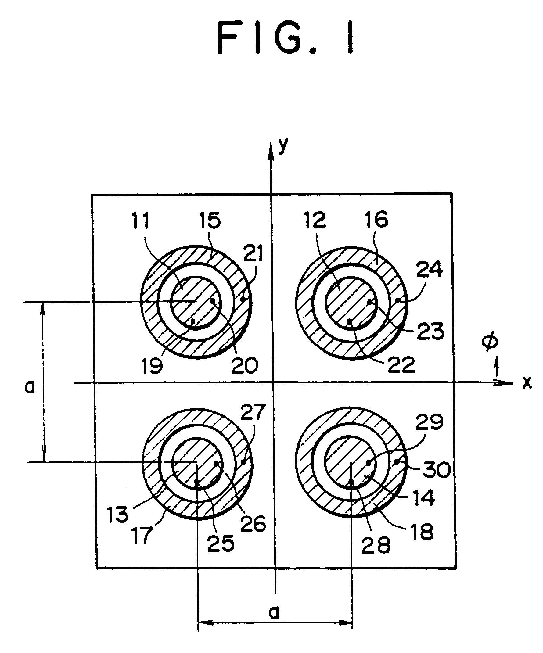
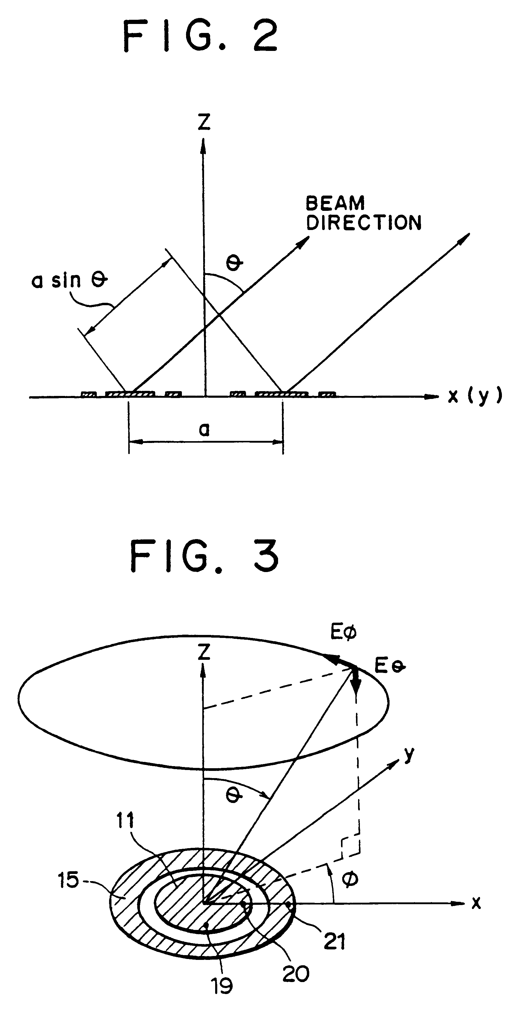
FIG. 1 is a top view showing a beam scanning antenna according to the present invention. In this embodiment, a vertically polarized radio wave (which has E.theta. component) is received. A beam is scanned in the directions of direction angles .phi.=0 degree, .+-.90 degrees, and 180 degrees on a plane tilted for an angle .theta. to the boresight (z direction) of the antenna. In this embodiment, the beam scanning antenna is an array antenna which is constructed of four antenna elements.

The antenna is constructed of dominant mode exciting antenna members 11 to 14 and higher-order mode exciting antenna members 15 to 18. Each antenna element is constructed of one dominant mode exciting antenna member and one higher-order mode exciting antenna member. Each antenna member is a pin-feed (coaxial feed) microstrip antenna member. The antenna has feed points 19 to 30. Each antenna element can radiate a beam in the direction of with an angle .theta. to the boresight (z direction) of the antenna...

second embodiment

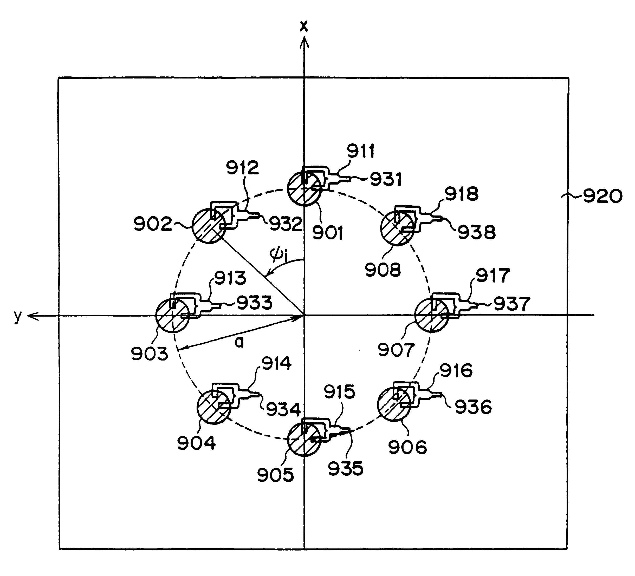
Next, the construction of a practical example of the above described beam scanning antenna and the feeding circuits thereof will be described. FIG. 17 is a top view showing the beam scanning antenna according to the present invention. FIG. 18 is a sectional view of FIG. 17.

As shown in FIG. 18, the beam scanning antenna according to the second embodiment is formed of 11 dielectric substrates 144 to 154 being layered. On the upper surface of the dielectric substrate 144, the circular microstrip antenna members 90 to 98, the ring microstrip antenna members 99 to 107, and the feed points 108 to 143 are formed, each of which is made of a conductor film. On the lower surface of the dielectric substrate 144, a ground conductor 253 is formed. The ground conductor 253 is made of a conductor film and functions as an antenna member. The dielectric substrates 145 and 146 forms a first dominant mode feeding circuit as a first tri-plate line pattern. The first tri-plate line pattern is formed of ...

third embodiment

Next, the present invention will be described.

In the second embodiment, even if the elevation angle to the boresight of the antenna is 60 degrees (namely, .theta.=60), the minimum value of the antenna element pitch is as large as 3.46 .lambda.. Thus, the area of the antenna becomes large. To solve this problem, in the third embodiment, the feeding circuit for the same mode is divided into two portions. The phases of the output signals of these portions are shifted for predetermined degrees. Thus, the antenna element pitch is decreased, thereby reducing the size of the entire antenna.

The construction of the third embodiment will be described with reference to the beam scanning antenna according to the second embodiment. The top view of the antenna according to the third embodiment is the same as that of the second embodiment shown in FIG. 12. In the case of the direction angles .phi.=.+-.45 degrees and .+-.135 degrees, the optical path difference [(2.sup.1 / 2 / 2).times.a.times.sin .th...


PUM


Abstract

An array antenna is formed of a plurality of antenna elements, each of which scans a beam in the direction of an angle theta to a boresight of the antenna and electrically varies the direction of a rotation angle phi of the beam. The antenna elements are disposed so that the optical path difference of radio waves transmitted or received by two adjacent antenna elements in the directions of a plurality of direction angles phi on the plane tilted for an angle theta to the boresight of the antenna is nearly a multiple of the wave length of the radio waves.

Description

1. Field of the InventionThe present invention relates to beam scanning antennas used for radar antennas, mobile communication antennas, satellite broadcasting receiving antennas, satellite-installed-antennas, and so forth.2. Description of the Related ArtIn antennas used for radars, mobile communications, satellite broadcasting reception, and so forth, a function which freely scans a beam in a desired direction is important. For example, when a mobile communication is performed, a mobile station (for example, an automobile or an airplane) is usually moving. Thus, a beam radiated from the antenna of the mobile station is not always directed to a predetermined direction. In this case, the beam of the antenna should be tracked to the predetermined direction (namely, the direction of an objective station which receives and / or transmits radio waves). As a means for scanning the beam of an antenna, the following methods have been employed.As a first method, a beam is scanned by a mechani...

Claims


Application Information

Patent Timeline
Patent Type & Authority Patents(United States)
IPC IPC(8): H01Q9/04H01Q3/26H01Q21/06H01Q3/36H01Q13/08
CPCH01Q3/26H01Q9/0428H01Q9/0464H01Q21/064H01Q21/065
Inventor SHOKI, HIROKI
Owner KK TOSHIBA
Why Eureka
Try Eureka