Method of and apparatus for real-time continual nanometer scale position measurement by beam probing as by laser beams and the like of atomic and other undulating surfaces such as gratings or the like relatively moving with respect to the probing beams

a technology of laser beams and beam probes, which is applied in the direction of instruments, measurement devices, and optical means, can solve the problems of significant incorrect position measurement, difficult to achieve atomic precision with this type of laser scale position encoder, and practicable limits, etc., to improve the response and operation of position sensing

Inactive Publication Date: 2003-10-28
NANOWAVE
View PDF4 Cites 342 Cited by
  • Summary
  • Abstract
  • Description
  • Claims
  • Application Information

AI Technical Summary

Benefits of technology

An additional object is to provide, also, improved position sensing response and operation particularly advantageous in such laser beam probing systems.

Problems solved by technology

Practical limits and precision in resolution are, however, being reached for reasons, including those which have been explained in said patents.
This means that an atomic level of precision is difficult to achieve with this type of laser scale position encoder.
Any changes of the beam path length caused by, for example, table tilting and laser wavelength shift, furthermore, will result in rather significant incorrect position measurement.
Gap changes between the head and the reference grating will usually either cause significant error of position measurement or no effect on the system due to symmetric optics location.
Thus, such cannot be used for multi-axis position measurement systems of the type described in my said patents.
While this generally provides better signal-to-noise ratio in measurement, the basic assumptions, like homogeneity of the temperature distribution and periodicity of the grating lines and spaces over such broad area, do not accurately hold, so as to achieve atomic precision (repeatability) in position measurement.
Such an approach, therefore, cannot be directly applied for position measurement purposes.

Method used


Image

  • Method of and apparatus for real-time continual nanometer scale position measurement by beam probing as by laser beams and the like of atomic and other undulating surfaces such as gratings or the like relatively moving with respect to the probing beams
  • Method of and apparatus for real-time continual nanometer scale position measurement by beam probing as by laser beams and the like of atomic and other undulating surfaces such as gratings or the like relatively moving with respect to the probing beams
  • Method of and apparatus for real-time continual nanometer scale position measurement by beam probing as by laser beams and the like of atomic and other undulating surfaces such as gratings or the like relatively moving with respect to the probing beams

Examples


Embodiment Construction

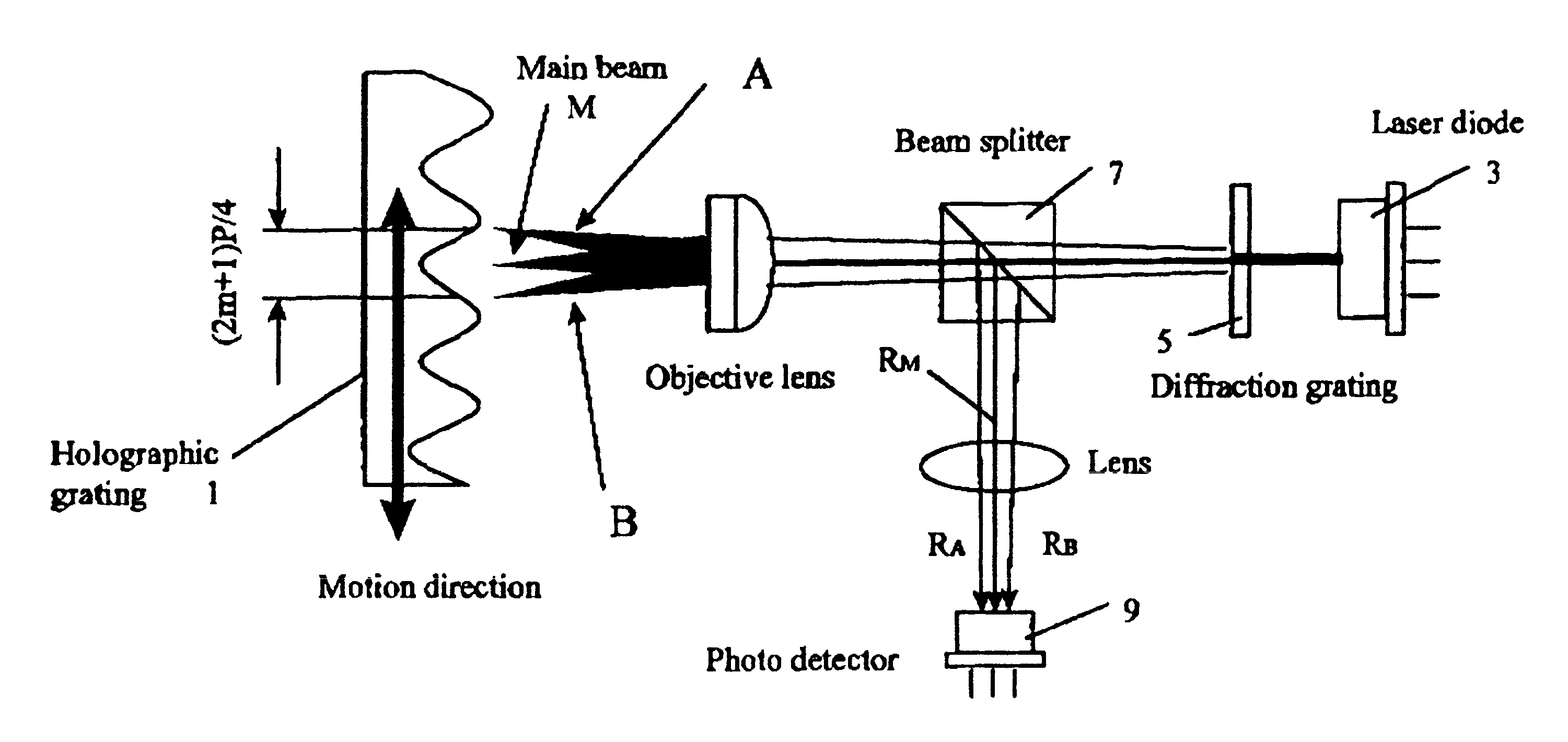
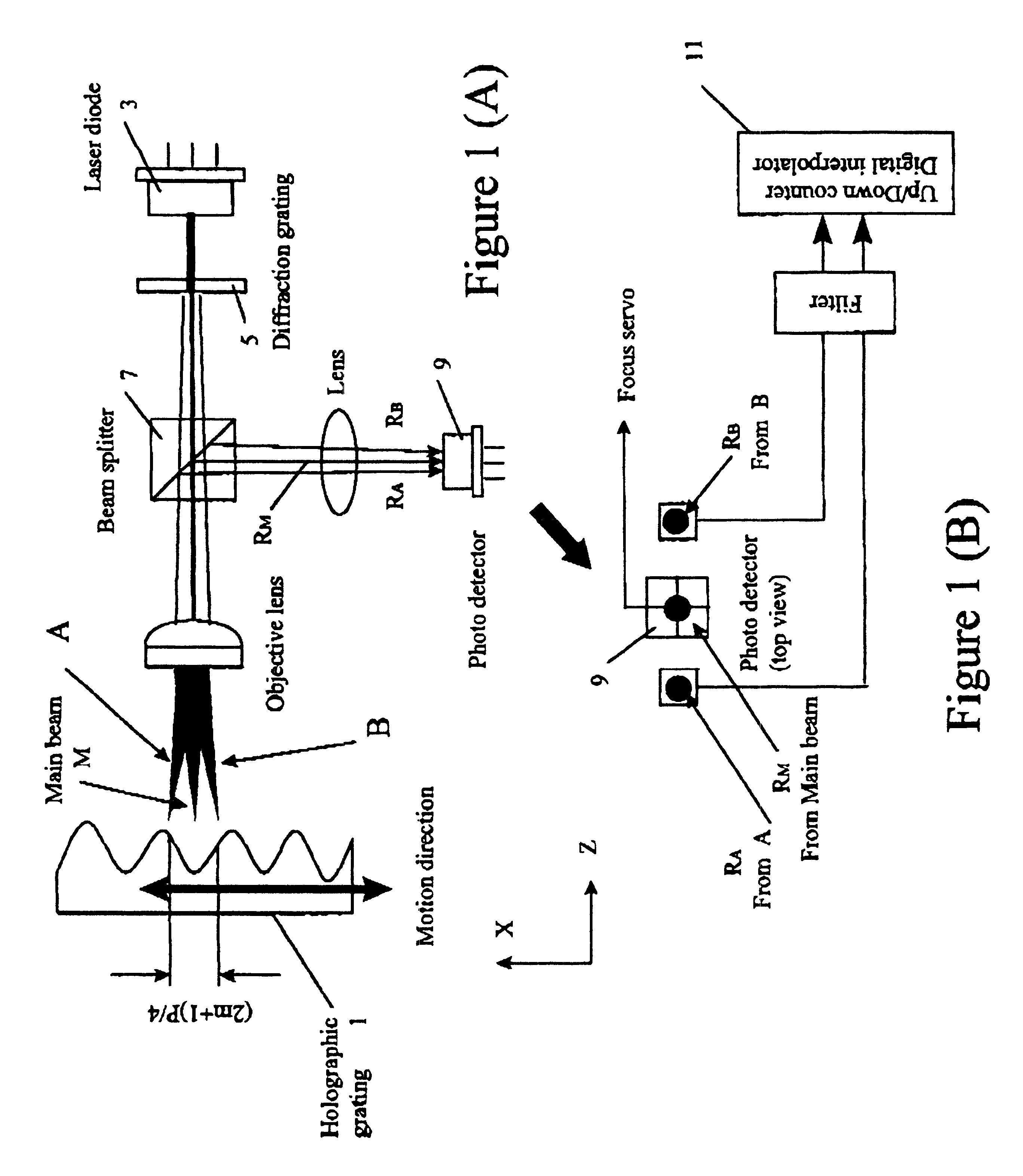
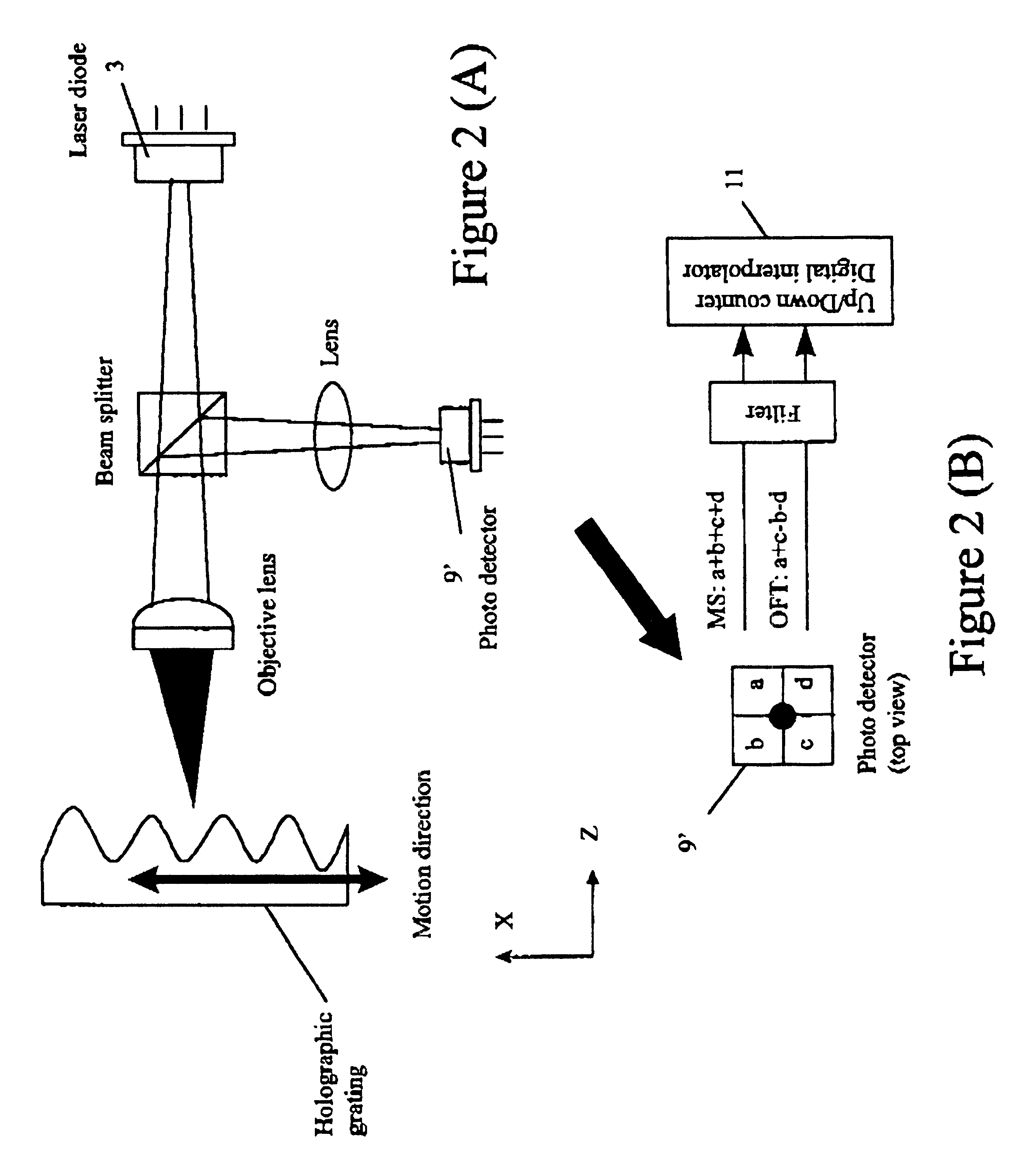
Turning first to the embodiment of FIG. 4, instead of the oscillating physical probe sensor used in certain embodiments of my said patents, there is shown a longitudinal-axis laser beam probe focused by the object lens L to impinge upon a holographic grating surface 1. The beam probe is shown in in FIG. 4 oscillated (up and down arrow) in two ways. One method is to vibrate the object lens L in the X-direction. A second method is to apply voltage, generated through a sinusoidal control signal D, to an acoustic-optic device A / O causing a diffraction angle change, or to an electro-optic device E / O causing a refractive index change. As a result, the focused laser beam spot moves correspondingly in the X-direction on the surface of grating 1. The laser beam, while it scans over the grating surface, is reflected back along the longitudinal axis to the beam splitter, so-labeled, from the successive points of the surface during the scan of the beam over the surface, and then transversely to...


PUM


Abstract

An improved method of and apparatus for real-time continual nanometer scale position measurement by beam probing as by laser beams and the like, both fixed and oscillating or scanning, over an atomic and other undulating surface such as gratings or the like, relatively moving with respect to the probing beams; and providing, where desired, increased detection speeds, improved positioning sensing response, freedom from or relaxed requirements of strict control on probing oscillation amplitude, and multi-dimensional position measurement with focused beam probes and the like.

Description

The present invention relates to nanometer and other inter-atomic position measurements and the like with the aid of probing sensors relatively moving with respect to periodically undulating atomic or other surfaces, such as gratings and the like, over which position locations are to be determined in real time.BACKGROUND OF INVENTIONLimitations in prior art laser beam interferometry measurements and similar prior optical probing techniques led to the development of oscillating sensing probes between which and such surfaces, sensing fields were established, relying upon the generation of sinusoidal output voltages measured after passing through the surface from the oscillation-controlled probe that, by comparison of the phase and amplitude of the oscillation controlling and resulting sinusoidal output voltages, enabled the development on a continual basis of positional signals indicative of the position of the probe along the surface, as described in my earlier U.S. Pat. Nos. 5,589,6...

Claims


Application Information

Patent Timeline
Patent Type & Authority Patents(United States)
IPC IPC(8): G12B21/00G12B21/06G12B21/02G01Q20/02G01Q60/18
CPCB82Y20/00G01Q60/18G01Q20/02B82Y35/00G01Q60/22
Inventor OHARA, TETSUO
Owner NANOWAVE
Why Eureka
Try Eureka