Additive manufacturing apparatus and method

a manufacturing apparatus and additive technology, applied in the field of additive manufacturing apparatus and methods, can solve the problem that the technique does not work with metal powder layers

Active Publication Date: 2016-08-18
RENISHAW PLC
View PDF6 Cites 232 Cited by
  • Summary
  • Abstract
  • Description
  • Claims
  • Application Information

AI Technical Summary

Benefits of technology

[0041]Shifting of the reflectivity of the mirror to be sufficiently reflective at wavelengths between 300 nm to 600 nm allows the mirror to be used to collect radiation emitted by a plasma formed through interaction of the laser beam with the powder material that is characteristic of the material that is present. This reflected radiation can then be separated from a path of the laser beam, for example by an optical splitter, and delivered to a detector, such as a spectrometer for analysing the radiation.
[0042]The mirror may comprise a multi-layer dielectric coating to provide the reflective performance.

Problems solved by technology

However, such a technique does not work with metal powder layers because such metal layers do not produce Raman spectra.

Method used


Image

  • Additive manufacturing apparatus and method
  • Additive manufacturing apparatus and method
  • Additive manufacturing apparatus and method

Examples


Embodiment Construction

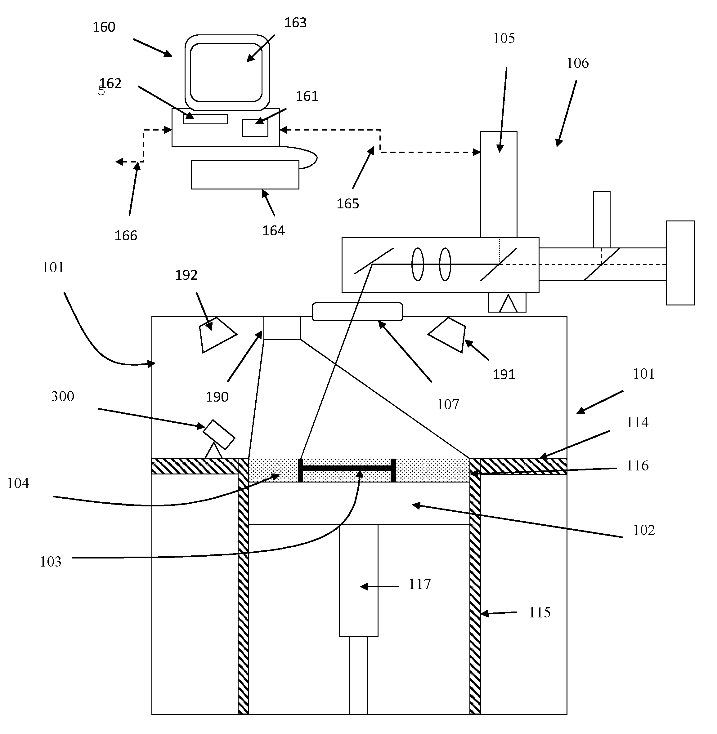
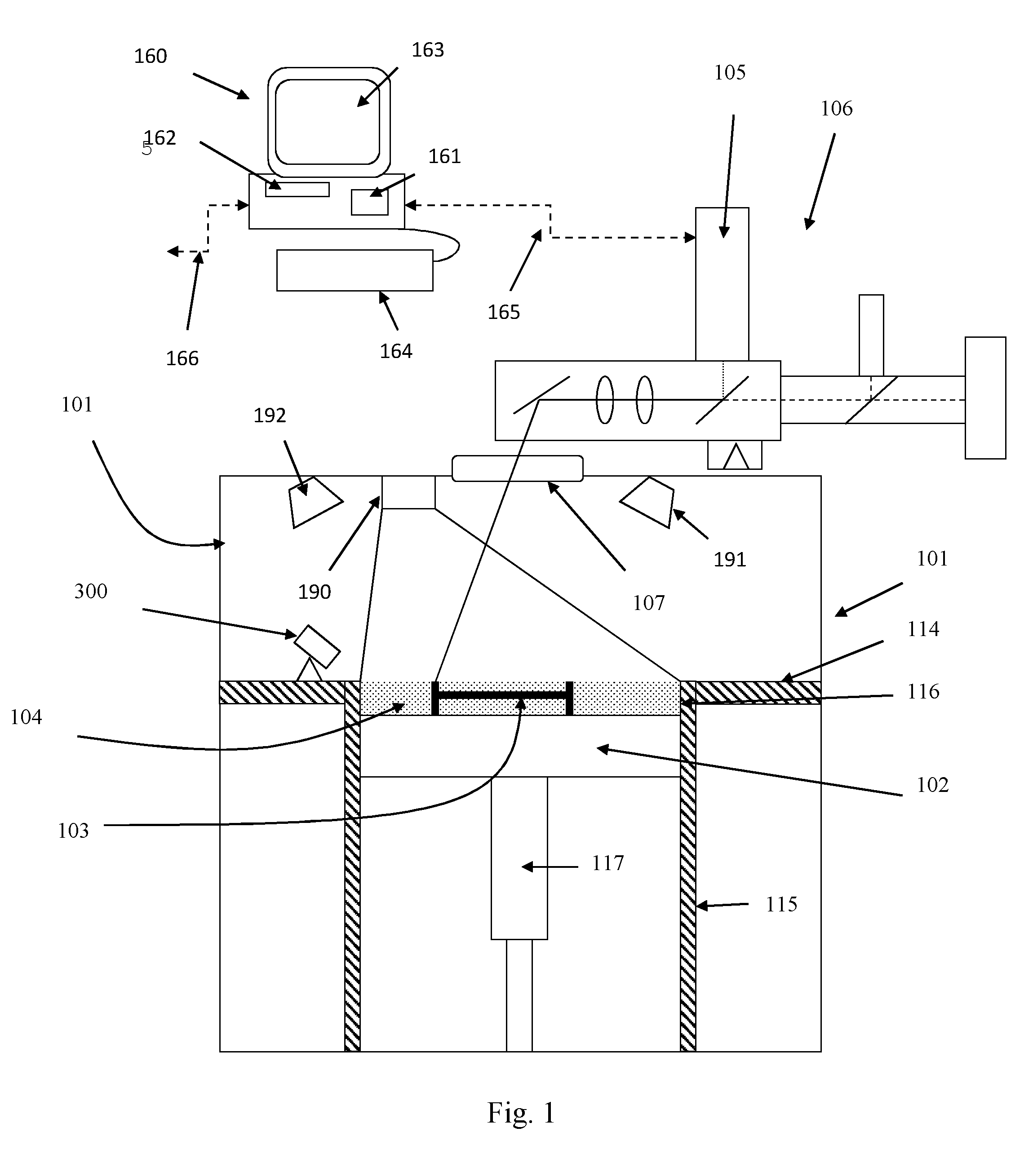
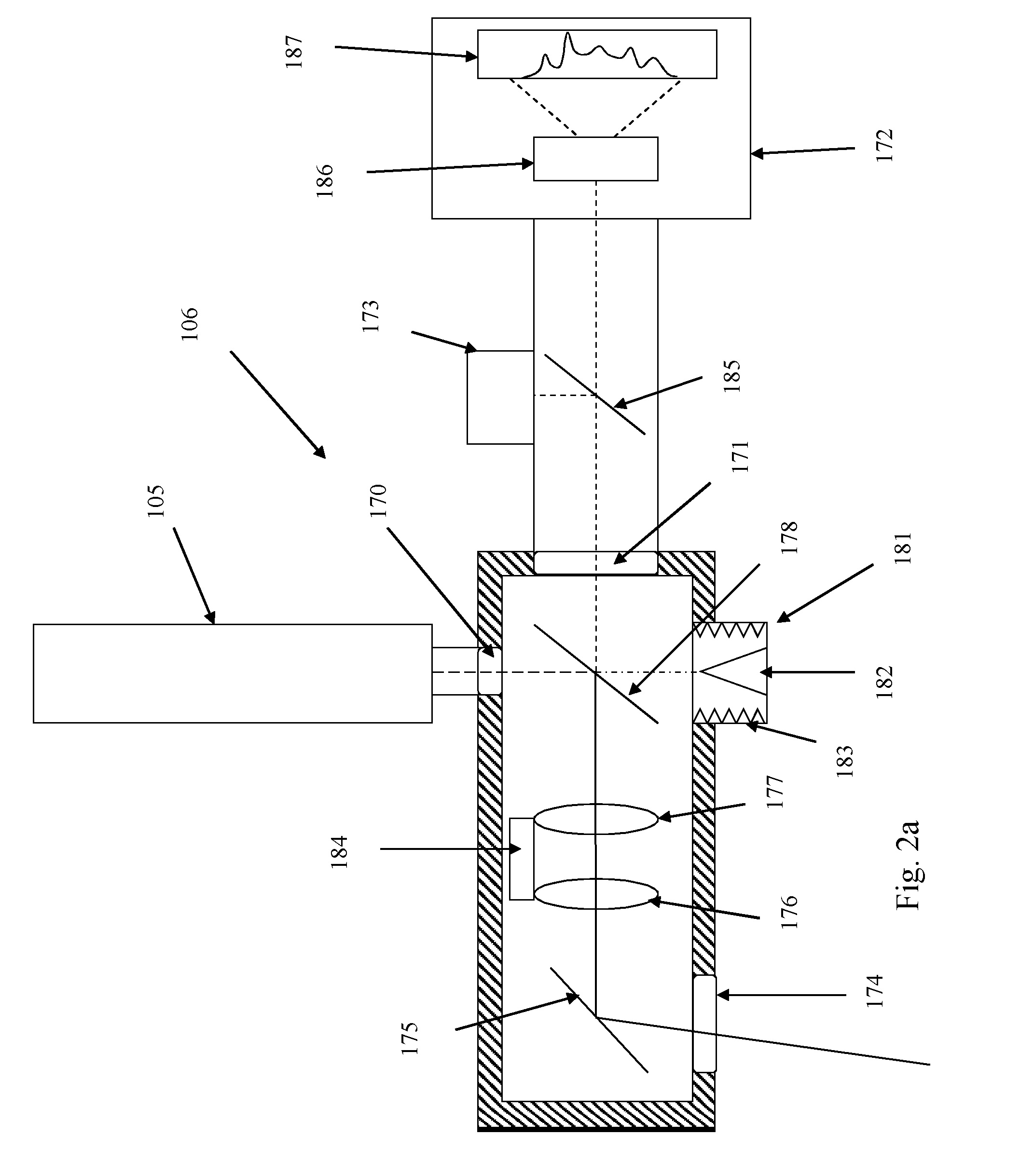
[0059]Referring to FIGS. 1 and 2, a selective laser melting (SLM) apparatus according to an embodiment of the invention comprises a build chamber 101 having therein partitions 114, 115 that define a build volume 116 and a surface onto which powder can be deposited. A build platform 102 defines a working area in which an object 103 is built by selective laser melting powder 104. The platform 102 can be lowered within the build volume 116 using mechanism 117 as successive layers of the object 103 are formed. A build volume available is defined by the extent to which the build platform 102 can be lowered into the build volume 116. Layers of powder 104 are formed as the object 103 is built by dispensing apparatus and a wiper (not shown). For example, the dispensing apparatus may be apparatus as described in WO2010 / 007396. A laser module 105 generates a laser for melting the powder 104, the laser directed onto the powder bed 104 as required by optical module 106 under the control of a co...


PUM

PropertyMeasurementUnit
wavelengthsaaaaaaaaaa
wavelength bandaaaaaaaaaa

Abstract

This invention concerns a laser solidification apparatus for building objects by layerwise solidification of powder material. The apparatus including a build chamber containing a build platform, a device for depositing layers of powder material on to the build platform, an optical unit for directing a laser beam to selectively solidify areas of each powder layer and a spectrometer for detecting characteristic radiation emitted by plasma formed during solidification of the powder by the laser beam. The invention also relates to a spectrometer for detecting characteristic radiation generated by interaction of the metal with the or a further laser beam. The spectra recorded using the spectrometer may be used for feedback control during the solidification process.

Description

FIELD OF INVENTION[0001]This invention concerns additive manufacturing apparatus and methods and has particular, but not exclusive application, to providing monitoring and in-process control of a selective laser solidification process, such as selective laser melting (SLM) or selective laser sintering (SLS).BACKGROUND[0002]Additive manufacturing or rapid prototyping methods for producing objects comprise layer-by-layer solidification of a material, such as a metal powder material, using a high energy beam, such as a laser beam. A powder layer is deposited on a powder bed in a build chamber and a laser beam is scanned across portions of the powder layer that correspond to a cross-section of the object being constructed. The laser beam melts or sinters the powder to form a solidified layer. After selective solidification of a layer, the powder bed is lowered by a thickness of the newly solidified layer and a further layer of powder is spread over the surface and solidified, as require...

Claims


Application Information

Patent Timeline
Patent Type & Authority Applications(United States)
IPC IPC(8): B22F3/105G01N21/71
CPCB22F3/1055B29C67/0077B29C67/0085B29C67/0088B22F2003/1057G01J3/28G01N21/274B33Y10/00B33Y30/00B33Y50/02G01N2201/06113G01N21/718Y02P10/295B29C64/153B29C64/393B29C64/268Y02P10/25B22F10/28B22F10/368B22F12/49B22F10/31B22F10/36B22F10/366B22F12/41B22F12/44B22F12/90B22F10/00
Inventor ASHTON, IAN ROBERT THOMASKLOSS, STEPHANSUTCLIFFE, CHRISTOPHERFERRAR, BEN IAN
Owner RENISHAW PLC
Why Eureka
Try Eureka