Optical recording medium

a recording medium and optical technology, applied in the field of optical recording mediums, can solve the problems of small difference in reflectivity, insufficient power of recording laser beam at the lower recording layer to form a good quality recording mark in the lower recording layer, etc., and achieve the effect of reducing production costs

Inactive Publication Date: 2007-08-30
TDK CORPARATION
View PDF1 Cites 4 Cited by
  • Summary
  • Abstract
  • Description
  • Claims
  • Application Information

AI Technical Summary

Benefits of technology

[0039]According to the present invention, it is possible to provide an optical recording medium that has a plurality of information layers whose recording sensitivities are close to each other and whose r

Problems solved by technology

Accordingly, when a recording laser beam with the same power level is irradiated onto each of the lower and upper recording layers, and when the lower and upper recording layers have the same recording sensitivity by themselves, the power of the recording laser beam at the lower recording layer may be insufficient to form a good quality recording mark in the lower recording layer.
Accordingly, recording layers that are too thick or too thin have a very small difference in reflectivity, so that it is hard to read the recording marks.
However, it is difficult to provide sufficient difference in reflectivity between the recording mark and the space in conventional recording layers made of an organic dye

Method used


Image

  • Optical recording medium
  • Optical recording medium
  • Optical recording medium

Examples


working example 1

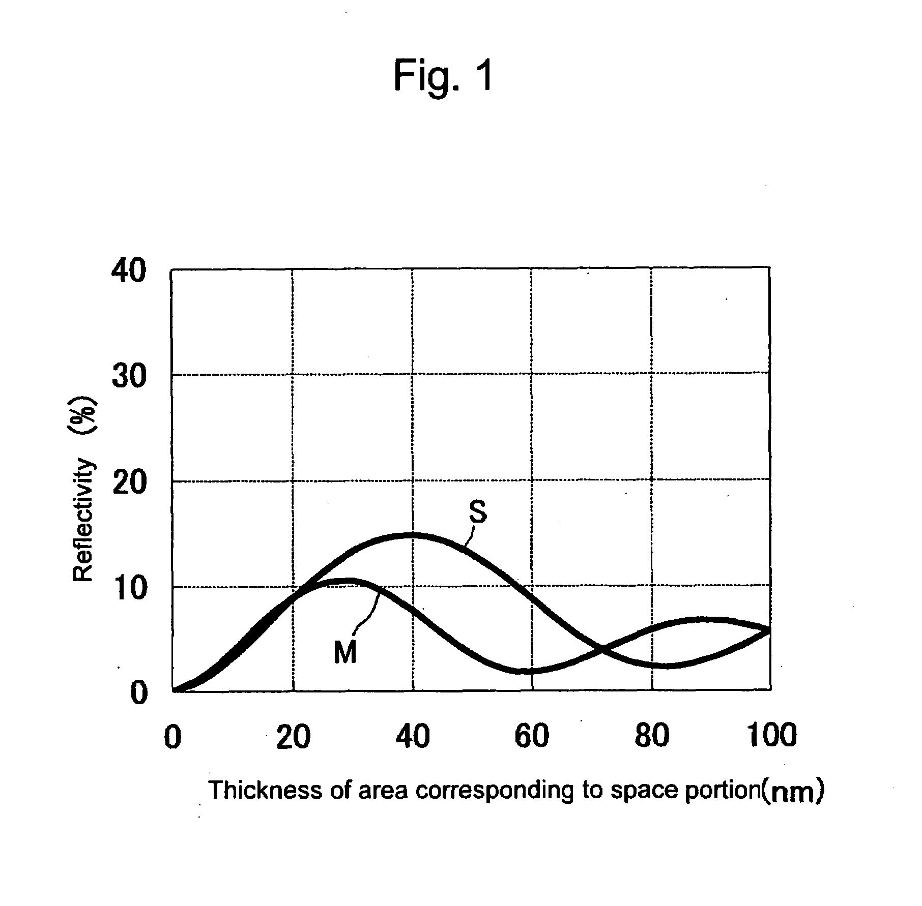
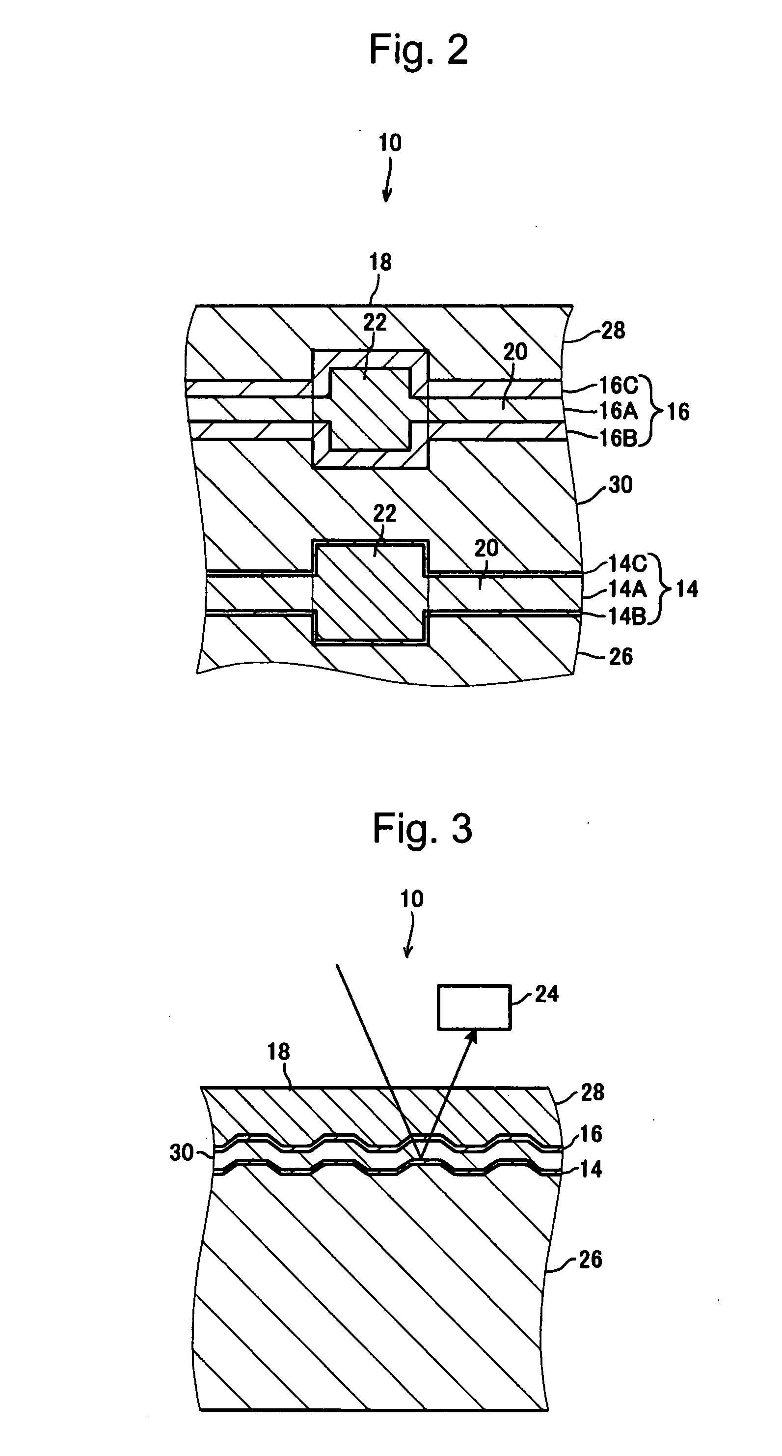
[0084]Three samples S1, S2, and S3 of one-sided optical recording media with two information layers, having the same structure as the optical recording medium 10 according to the first exemplary embodiment, were manufactured. The samples S1, S2, and S3 differed from each other in the thicknesses of the dielectric layers 16B and 16C of the second information layer 16, and the specifications other than the dielectric layers 16B and 16C were the same for all these samples.

[0085]Specifically, the recording layer 14A of the first information layer 14 and the recording layer 16A of the second information layer 16 were made of bismuth and oxygen, where the ratio of the number of oxygen atoms to the number of constituent atoms in the recording layers 14A and 16A was 71% (being not less than 63%), the ratio of the number of bismuth atoms to the number of constituent atoms in the recording layers was 29%, and there were no additional elements. The deposition conditions for the recording layer...

working example 2

[0097]A sample S4 having a recording layer 16A of second information layer 16 of 31 nm, being thinner than that of the sample S3 in Working Example 1 by 2 nm, was manufactured. The other specifications of the sample S4 were the same as those of the sample S3.

[0098]The reflectivities, recording sensitivity, and 8T C / N ratio of the first information layer 14 and the second information layer 16 were measured for the sample S4 in the same manner as Working Example 1. The measurement results are shown together with the structure of the first information layer 14 and the second information layer 16 for the sample S4 in Table 1.

working example 3

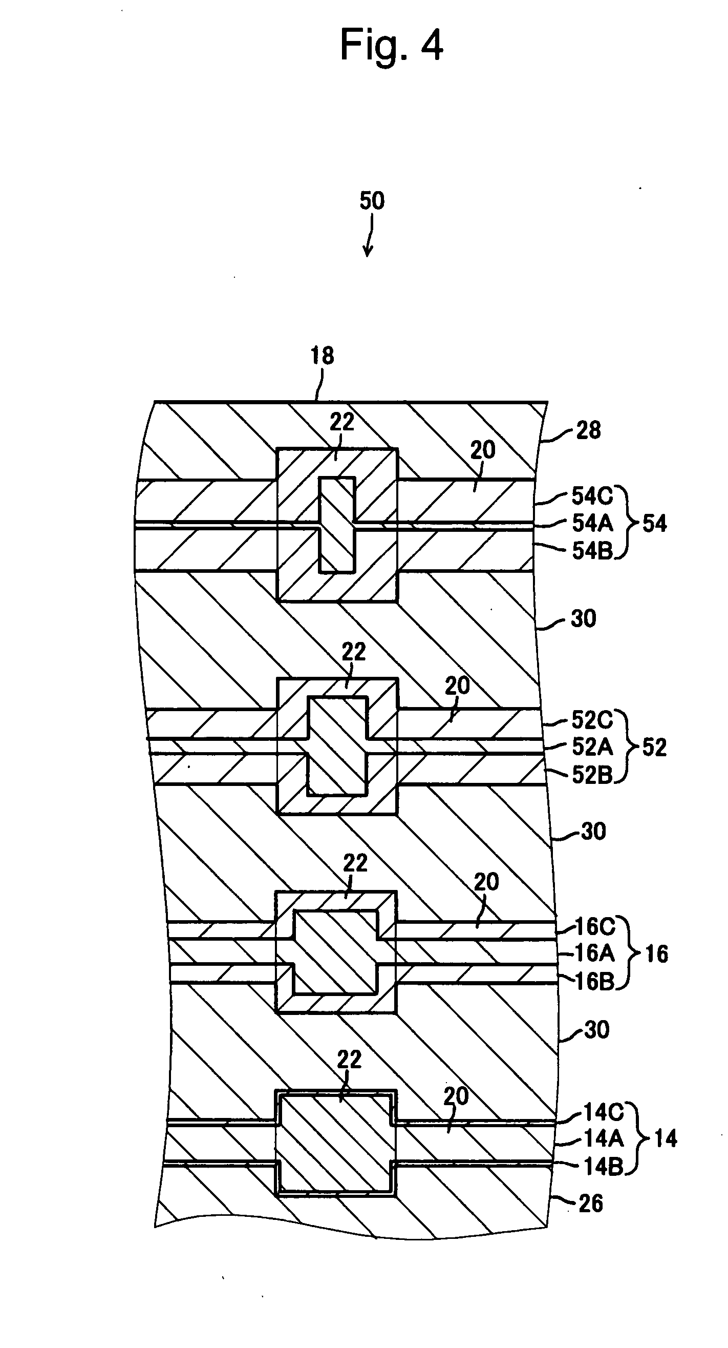
[0099]Two samples S5 and S6 of one-sided optical recording media with four information layers, having the same structure as the optical recording medium 50 according to the second exemplary embodiment, were manufactured. The samples S5 and S6 differed from each other only in the third information layer 52 and the fourth information layer 54, and the specifications other than the information layers 52 and 54 were the same for the samples S5 and S6. The composition and deposition conditions of the recording layers 14A, 16A, 52A, and 54A of the samples S5 and S6 were the same as those of the recording layers 14A and 16A of the samples S1, S2, and S3 in Working Example 1. The composition and deposition conditions of the dielectric layers 14B, 14C, 16B, 16C, 52B, 52C, 54B, and 54C of the samples S5 and S6 were also the same as those of the dielectric layers 14B, 14C, 16B, and 16C of the samples S1, S2, and S3 in Working Example 1.

[0100]The reflectivities, recording sensitivity, and 8T C / ...


PUM


Abstract

An optical recording medium is provided which includes a plurality of information layers having recording sensitivities close to each other and reflectivities close to each other, and a sufficient difference in reflectivity between a space portion and a recording mark, and provides a reduction in production costs. The optical recording medium includes a first and a second information layer. Recording marks thicker than a space portion are formed in the information layers. The recording layer of the first information layer which is placed far from an incident surface is thicker than the recording layer of the second information layer which is placed close to the incident surface. The total thickness of dielectric layers of the first information layer is smaller than the total thickness of dielectric layers of the second information layer. The first information layer is thinner than the second information layer.

Description

BACKGROUND OF THE INVENTION[0001]1. Field of the Invention[0002]The present invention relates to an optical recording medium having a plurality of recording layers.[0003]2. Description of the Related Art[0004]Optical recording media such as compact discs (CDs) and digital versatile discs (DVDs) are widely utilized as information recording media. In particular, some types of optical recording media which utilize a blue or blue-violet laser as the irradiation light to allow for the recording of far more information than conventional lasers are becoming popular.[0005]The optical recording media are generally classified into three types: a read-only memory (ROM) type, which can neither record nor rewrite data, a rewritable (RW) type, which can rewrite data, and a recordable (R) type, which can record data only once.[0006]In the R-type optical recording media, a laser beam, when being irradiated onto a portion of a recording layer, increases or decreases reflectivity of that portion as c...

Claims


Application Information

Patent Timeline
IPC IPC(8): B32B3/02G11B7/24035G11B7/24038G11B7/243G11B7/2433G11B7/2542
CPCG11B7/24038G11B2007/2432G11B2007/24314G11B7/2542
Inventor MISHIMA, KOJIYOSHITOKU, DAISUKETANAKA, KAZUSHI
Owner TDK CORPARATION
Why Eureka
Try Eureka