Eureka AIR delivers breakthrough ideas for toughest innovation challenges, trusted by R&D personnel around the world.

Tractor Lift Arm Stabilizer

Inactive Publication Date: 2013-05-09
KING KUTTER
View PDF13 Cites 0 Cited by
  • Summary
  • Abstract
  • Description
  • Claims
  • Application Information

AI Technical Summary

Benefits of technology

This patent describes a device that attaches to tractor lift arms to keep them stable and prevent movement during certain operations. The device, called a stabilizer, adds rigidity to the lift arms to improve their performance.

Problems solved by technology

Certain tractor operations and / or implements may cause the lift arms to sway from side to side.

Method used


Image

  • Tractor Lift Arm Stabilizer
  • Tractor Lift Arm Stabilizer
  • Tractor Lift Arm Stabilizer

Examples


Embodiment Construction

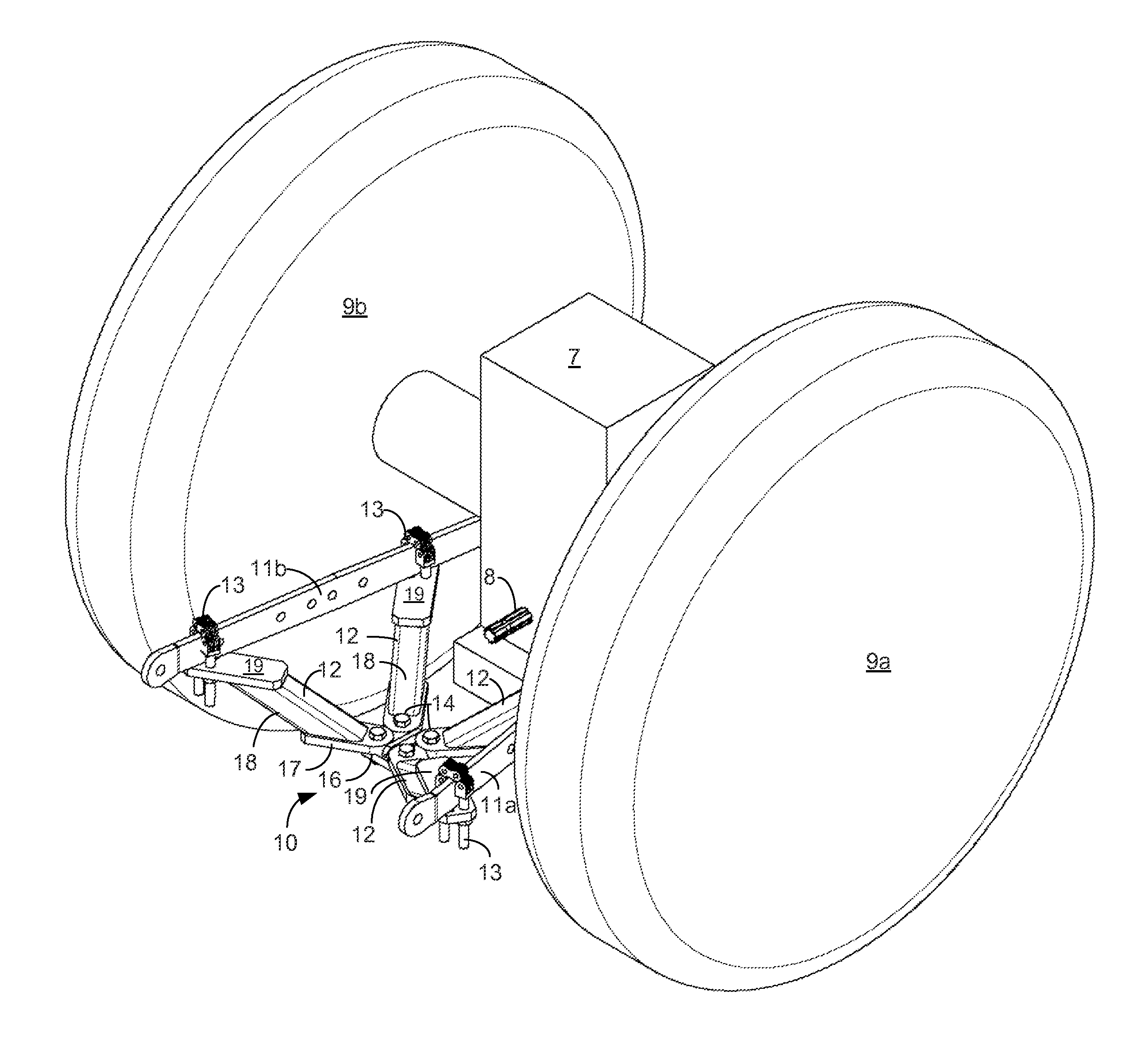
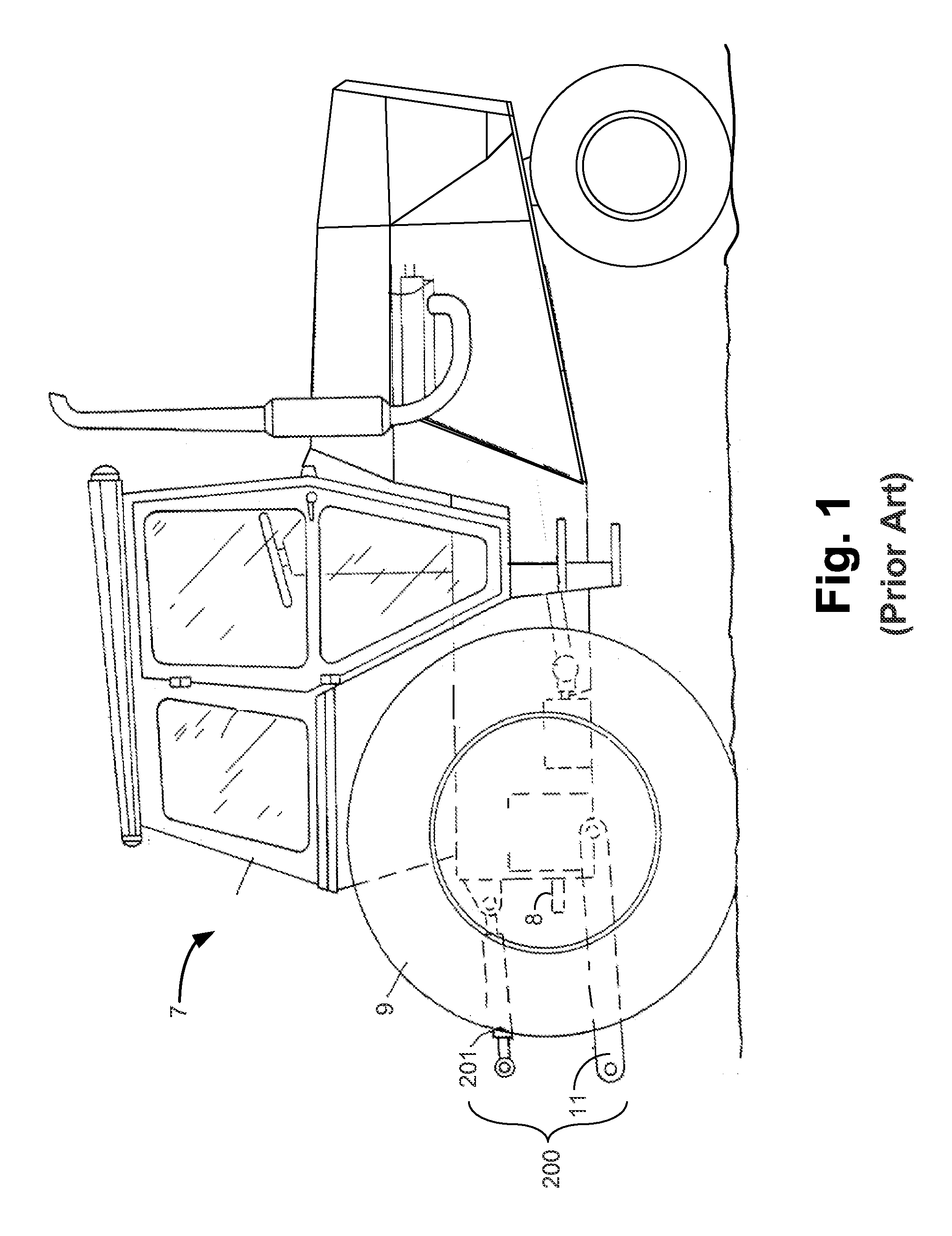
[0037]FIG. 1 depicts a prior art tractor 7 comprising a three point hitch 201 that is known in the art. As known by persons of skill in the art, the three point hitch 200 of the tractor 7 comprises the two substantially similar lift arms 11 (only one of which is shown FIG. 14) and a top link 201. The three point hitch 200 is disposed between the rear wheels 9 (only one of which is shown in FIG. 1) of the tractor 7.

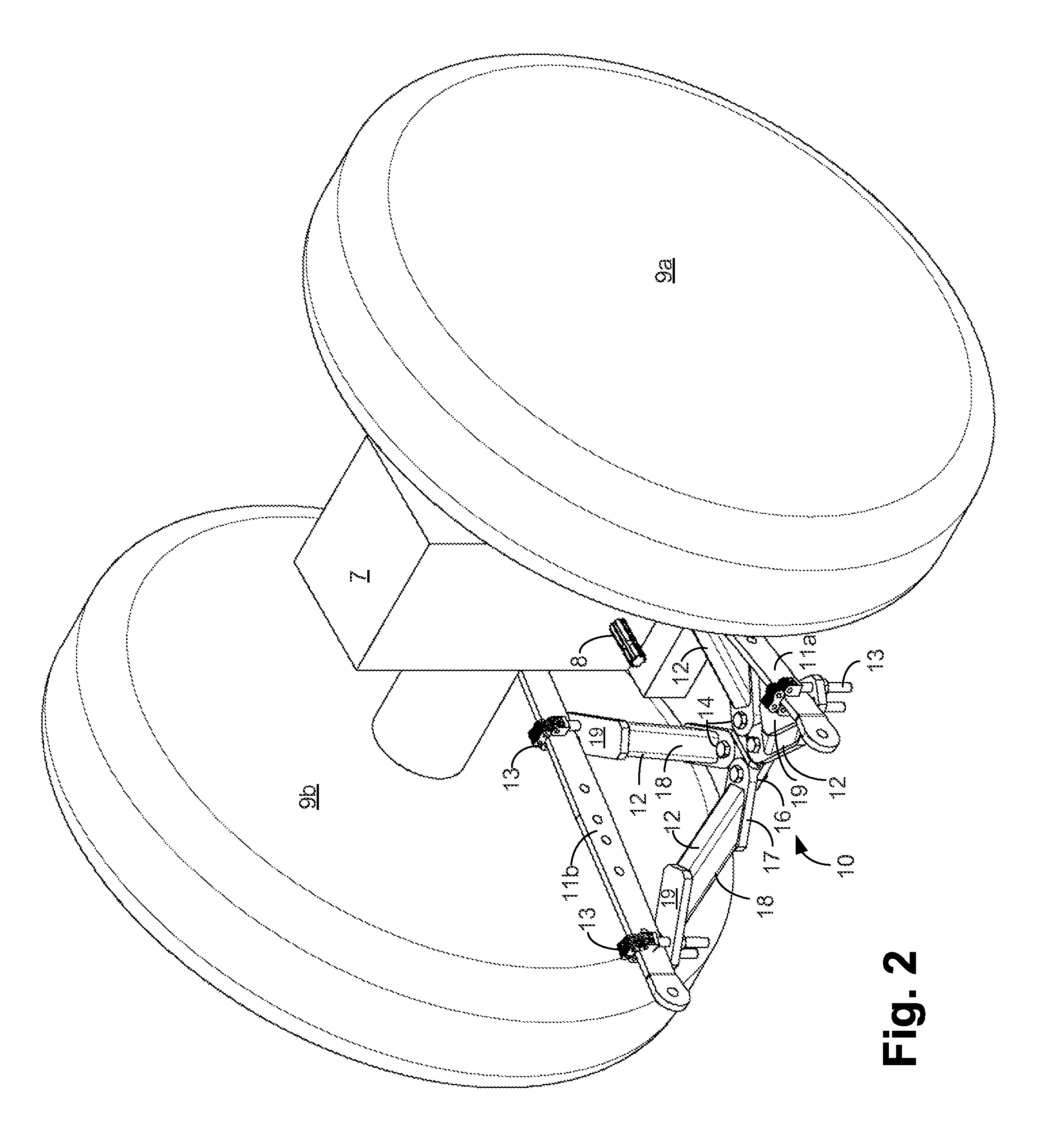
[0038]A power take-off (PTO) 8 extends from the tractor 7 generally between the rear wheels 9 of the tractor 7. As is known by persons of skill in the art, the PTO 8 is a splined driveshaft on a tractor or truck that is used to provide power, in the form of rotation, to an attachment, such as a farming implement (not shown), or to separate machines. A drive line (not shown) that is known in the art extends between the PTO 8 and the attachment and translates rotation from the PTO to the attachment.

[0039]FIG. 2 depicts a stabilizer 10 according to an embodiment of the presen...


PUM


Abstract

An apparatus for stabilizing at least two lift arms on a tractor has a center portion disposed below the power take-off of the tractor. A plurality of angled legs connect to and extend downwardly from the lift arms. A space is formed by the angled legs to allow for connection of an implement to the PTO of the tractor.

Description

CROSS-REFERENCE TO RELATED APPLICATIONS[0001]This application is a continuation-in-part of and claims priority to U.S. Non-provisional patent application Ser. No. 13 / 024,201, filed on Feb. 9, 2011, the entire contents of which are incorporated by reference. This application claims the benefit of U.S. Provisional Application No. 61 / 302,803 titled “Tractor Lift Arm Stabilizer,” filed on Feb. 9, 2010, the entire contents of which are herein incorporated by reference.BACKGROUND AND SUMMARY OF THE INVENTION[0002]A stabilizer for the lift arms of a tractor is provided. Two lift arms and a center top link make up the three “points” of the tractor's three point hitch. The lift arms are controlled by a hydraulic system of the tractor, which provides lifting and lowering of the lift arms. The three point hitch is used to connect farming implements and other implements to the tractor.[0003]Certain tractor operations and / or implements may cause the lift arms to sway from side to side. A stabili...

Claims


Application Information

Patent Timeline
IPC IPC(8): A01B59/041
CPCA01B59/041
Inventor FRALEY, J. PHILLIPDAVIS, JOHN W.
Owner KING KUTTER
Why Eureka
Eureka Blog
Learn More