Liquid ejecting apparatus and liquid ejecting method

a liquid ejecting apparatus and liquid ejecting technology, which is applied in the direction of printing, inking apparatus, other printing apparatus, etc., can solve the problems of unstable liquid ejecting, insufficient ejecting amount, and inability to eject liquid, so as to achieve efficient ejecting of high viscosity liquid

Inactive Publication Date: 2013-06-20
SEIKO EPSON CORP
View PDF2 Cites 0 Cited by
  • Summary
  • Abstract
  • Description
  • Claims
  • Application Information

AI Technical Summary

Benefits of technology

[0007]An advantage of some aspects of the invention is to efficiently eject the high viscosity liquid.

Problems solved by technology

When the high viscosity liquid is ejected from the nozzle including the taper portion and the straight portion, sometimes the ejection of the liquid becomes unstable.
For example, the liquid may not be ejected, and an ejection amount may be insufficient.
Various factors can be considered which make the ejection unstable.
One of the factors is that a pressure of the liquid within the pressure chamber is not efficiently applied to eject the liquid.

Method used


Image

  • Liquid ejecting apparatus and liquid ejecting method
  • Liquid ejecting apparatus and liquid ejecting method
  • Liquid ejecting apparatus and liquid ejecting method

Examples


first embodiment

Regarding Printing System

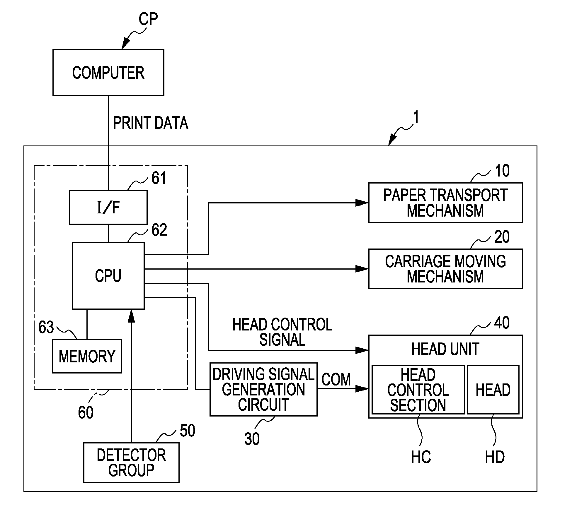
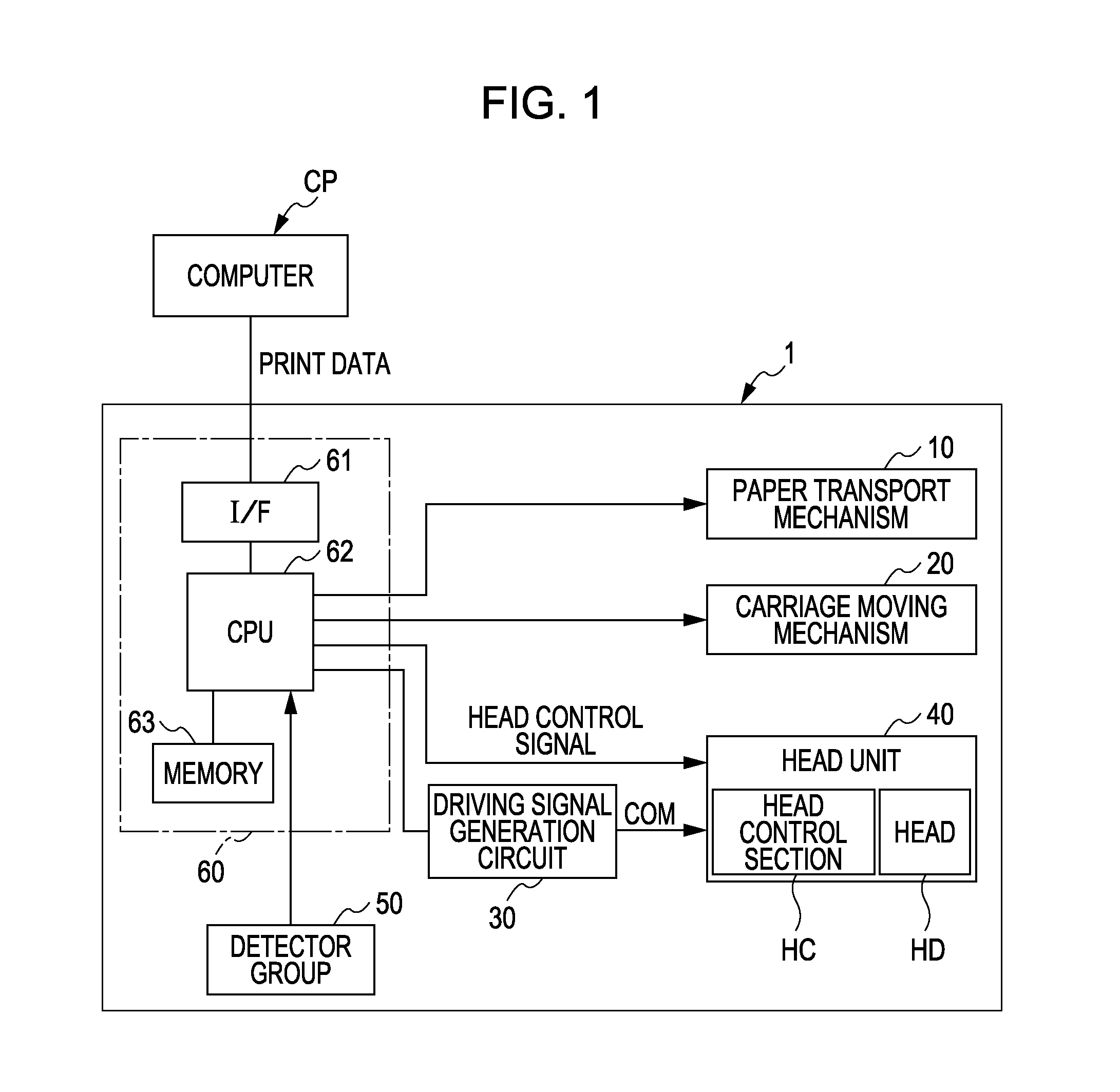
[0067]The printing system exemplified in FIG. 1 includes a printer 1 and computer CP. The printer 1 corresponds to a liquid ejecting apparatus, and ejects an ink as a liquid toward a medium such as a paper, a cloth, and a film. The medium is a target object which is a target of the liquid ejection. The computer CP is connected so as to be able to communicate with the printer 1. In order to make the printer 1 print an image, the computer CP transmits print data based on the image to the printer 1.

Outline of Printer 1

[0068]The printer 1 includes a paper transport mechanism 10, a carriage moving mechanism 20, a driving signal generation circuit 30, a head unit 40, a detector group 50, and a printer controller 60.

[0069]The paper transport mechanism 10 transports a paper in a transport direction. The carriage moving mechanism 20 moves a carriage, on which the head unit 40 is mounted, in a predetermined moving direction (for example, a widthwise direction of the p...

application examples

Regarding Other Application Examples

[0126]Further, in the above-mentioned embodiments, the printer 1 was described as a liquid ejecting apparatus, but this does not limit the invention. For example, the same technique as the embodiment may be applied to various liquid ejecting apparatuses, which use inkjet techniques, such as a color filter manufacturing apparatus, a dyeing apparatus, a microscopic processing apparatus, semiconductor manufacturing apparatus, a surface processing apparatus, a three-dimensional modeling apparatus, a liquid evaporation apparatus, an organic EL manufacturing apparatus (particularly, a polymer EL manufacturing apparatus), a display manufacturing apparatus, coating apparatus, a DNA chip manufacturing apparatus. Further, methods therefor and manufacturing methods are also included in an allowable application range.


PUM


Abstract

A liquid ejecting apparatus includes: a pressure chamber that communicates with a liquid supply section and a nozzle; an element that changes a pressure of liquid within the pressure chamber; and an ejection pulse generation section that generates an ejection pulse for operating the element to eject the liquid from the nozzle. The viscosity of the liquid is not less than 8 millipascal seconds. The nozzle has a first portion in which a liquid ejection side thereof has a smaller opening area than a pressure chamber side thereof, and a second portion which communicates with an ejection side end portion of the first portion. The ejection pulse has a depressurizing portion for depressurizing the liquid to attract a meniscus positioned on the second portion to the first portion, and a pressurizing portion for pressurizing the liquid to eject the liquid before the meniscus returns to the second portion.

Description

[0001]This application is a continuation of U.S. patent application Ser. No. 12 / 611,747, filed Nov. 3, 2009, which claims priority to Japanese Patent Application No. 2008-284631, filed Nov. 5, 2008, the entireties of which are incorporated by reference herein.BACKGROUND[0002]1. Technical Field[0003]The present invention relates to a liquid ejecting apparatus and a liquid ejecting method.[0004]2. Related Art[0005]Recently, an inkjet printer technique has been applied to eject a liquid (it is referred to as a high viscosity liquid) having a viscosity higher than that of the water-based ink which is usually used. For example, there has been proposed an apparatus in which a nozzle for ejecting liquid includes a taper portion tapering off toward the ink ejection side and a straight portion disposed successively from the tip of the ejection side of the taper portion (for example, refer to Japanese Unexamined Patent Application Publication No. 2004-90223).[0006]When the high viscosity liqu...

Claims


Application Information

Patent Timeline
Patent Type & Authority Applications(United States)
IPC IPC(8): B41J2/045
CPCB41J2/04581B41J2/04588B41J2202/11B41J29/38B41J2/14274
Inventor OZAWA, KINYA
Owner SEIKO EPSON CORP
Why Eureka
Try Eureka