Liquid ejecting head and manufacturing method of liquid ejecting head

a technology of liquid ejecting head and manufacturing method, which is applied in printing and other directions, can solve the problems of liquid ejecting, and achieve the effect of easy valve mechanism formation

Active Publication Date: 2016-08-23
SEIKO EPSON CORP
View PDF4 Cites 0 Cited by
  • Summary
  • Abstract
  • Description
  • Claims
  • Application Information

AI Technical Summary

Benefits of technology

[0008]An advantage of some aspects of the invention is to provide a liquid ejecting head capable of efficiently ejecting a liquid, and a manufacturing method of the liquid ejecting head.
[0010]In this case, it is possible to efficiently transmit the pressure change within the pressure chamber to the nozzle side when the liquid is ejected from the nozzle. As a result, it is possible to efficiently eject the liquid from the nozzle.
[0012]In this case, it is possible to simplify the configuration of the valve mechanism.
[0014]In this case, it is possible to more reliably prevent the flowing out of the liquid to the reservoir side.
[0018]In this case, it is possible to easily form the valve mechanism.

Problems solved by technology

Due to the counterflow of a portion of the liquid, it may not be possible to eject the liquid from the nozzles by efficiently using the pressure fluctuation caused by the piezoelectric elements.

Method used


Image

  • Liquid ejecting head and manufacturing method of liquid ejecting head
  • Liquid ejecting head and manufacturing method of liquid ejecting head
  • Liquid ejecting head and manufacturing method of liquid ejecting head

Examples


second embodiment

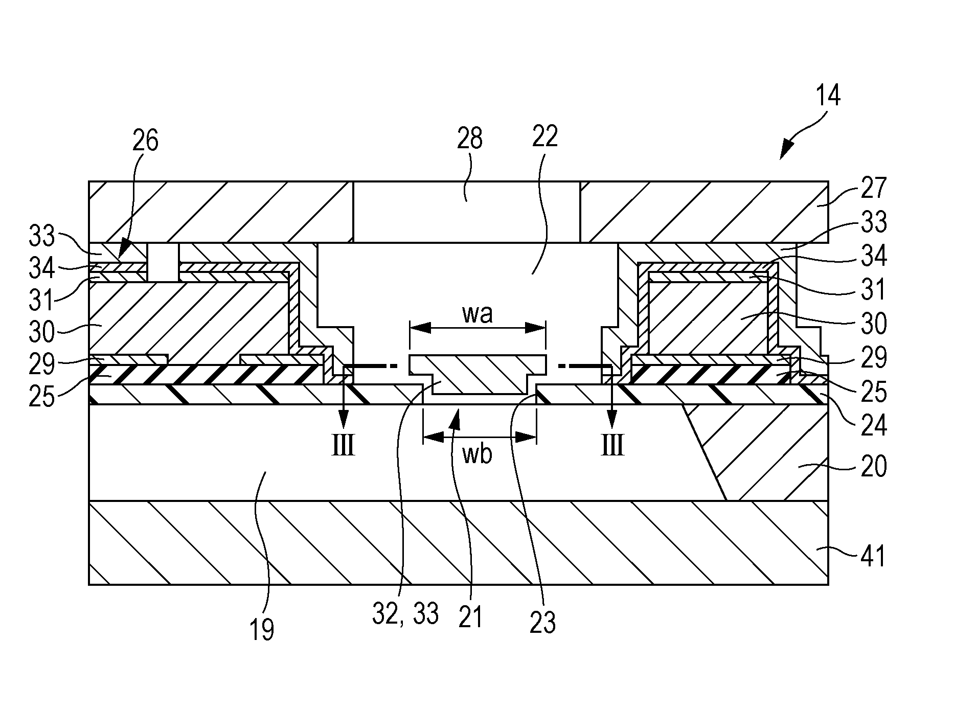
[0063]Incidentally, the configuration in which the valve mechanism is provided in a region which is distanced from the region which is between the reservoir and the pressure chamber and in which the piezoelectric element of the diaphragm of the recording head is laminated is not limited to the embodiment described above. In the second embodiment illustrated in FIGS. 9A and 9B, the valve mechanism 46 is formed on the bottom side (the opposite side from a pressure chamber 19′) of a communication substrate 41′.

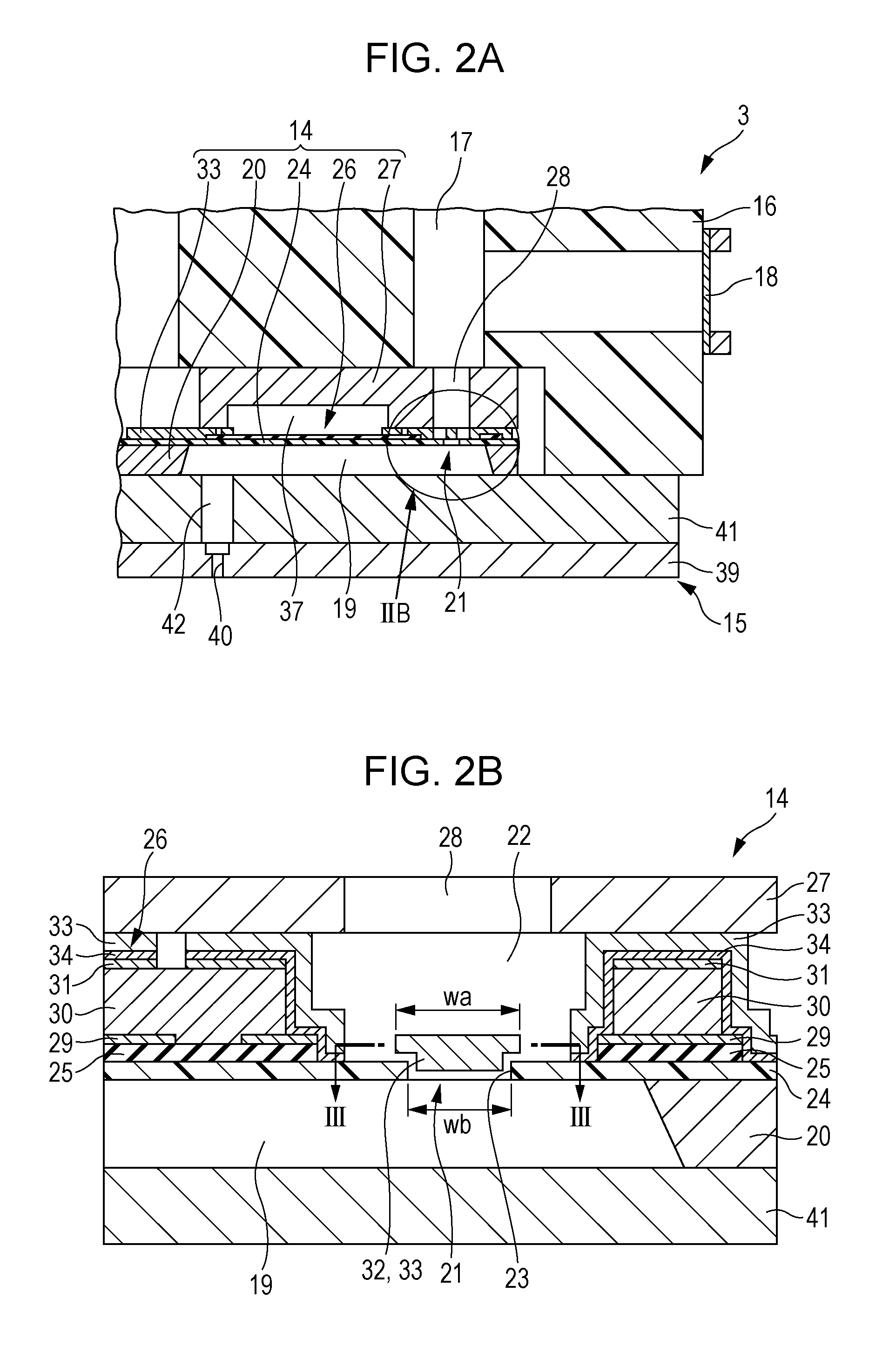
[0064]FIG. 9A is a cross sectional diagram illustrating the configuration of a recording head 3′ in the second embodiment, and FIG. 9B is an enlarged diagram illustrating region IXB in FIG. 9A. As illustrated in FIG. 9A, the recording head 3′ in the present embodiment is also provided with a pressure generation unit 14′ and a channel unit 15′, and is configured to be attached to a head case 16′ in a state in which the members are laminated together.

first embodiment

[0065]As opposed to in the first embodiment described above, no reservoir is formed on the inner portion of the head case 16′ of the present embodiment, and, as illustrated in FIG. 9A, a liquid supply path 44 which supplies the ink to the reservoir 45 is formed on the inner portion of the head case 16′. The ink which flows from the ink cartridges 7 into the recording head 3′ flows into the reservoir 45 which is positioned below the head case 16′ via the liquid supply path 44.

[0066]In the same manner as in the first embodiment described above, the pressure generation unit 14 forms a unit by a pressure chamber forming substrate 20′, a diaphragm 24′, a piezoelectric element 26′, a protective substrate 27′, and the like being laminated together; however, the valve mechanism is not provided. In other words, an opening is not provided in the diaphragm 24′ which partitions the top surface of the pressure chamber forming substrate 20′, and the valve space is not formed. Therefore, the openi...


PUM

PropertyMeasurementUnit
thickaaaaaaaaaa
flexibleaaaaaaaaaa
pressureaaaaaaaaaa

Abstract

A liquid ejecting head includes a nozzle which ejects a liquid, a pressure chamber, a portion of which is partitioned by a flexible diaphragm and which communicates with the nozzle, a piezoelectric element which is laminated on an opposite side of the diaphragm from the pressure chamber and changes a pressure within the pressure chamber, and a reservoir which communicates with the pressure chamber, in which a valve mechanism is provided in a region which is distanced from a region in which the piezoelectric element of the diaphragm is laminated, and is configured to allow the liquid to flow from the reservoir side into the pressure chamber side while inhibiting the liquid from flowing out from the pressure chamber side to the reservoir side.

Description

CROSS-REFERENCE TO RELATED APPLICATIONS[0001]The entire disclosure of Japanese Patent Application No: 2014-125059, filed Jun. 18, 2014 is expressly incorporated by reference herein in its entirety.BACKGROUND[0002]1. Technical Field[0003]The present invention relates to a liquid ejecting head which ejects a liquid within a pressure chamber from a nozzle which communicates with the pressure chamber, and a manufacturing method of the liquid ejecting head.[0004]2. Related Art[0005]A liquid ejecting apparatus is an apparatus which is provided with a liquid ejecting head and which ejects various liquids from an ejecting head. An image recording apparatus such as an ink jet printer or an ink jet plotter is an example of the liquid ejecting apparatus; however, recently liquid ejecting apparatuses are also being adapted for use in various manufacturing apparatuses, making use of the characteristic of being capable of causing minute amounts of a liquid to accurately land on predetermined posi...

Claims


Application Information

Patent Timeline
Patent Type & Authority Patents(United States)
IPC IPC(8): B41J2/14B41J2/16
CPCB41J2/14233B41J2/161B41J2002/14419Y10T29/49403B41J2/1621B41J2/14201B41J2002/14306
Inventor NAGANUMA, YOICHIHIRAI, EIJU
Owner SEIKO EPSON CORP
Why Eureka
Try Eureka