Switching Power Supply Device and Light-Emitting Diode Lighting Device

a technology of switching power supply and light-emitting diodes, which is applied in the direction of semiconductor lamp usage, dc conversion, electroluminescent light sources, etc., can solve the problems of not revealing a technique of raising the stability of the power supply against a wide range of variation in ac input voltage, increasing maintenance-parts cost and the like of the switching power supply device and the led lighting device, so as to reduce the design cost, manufacturing cost and the like of the switching

Active Publication Date: 2013-06-27
MINEBEAMITSUMI INC
View PDF3 Cites 23 Cited by
  • Summary
  • Abstract
  • Description
  • Claims
  • Application Information

AI Technical Summary

Benefits of technology

[0029]When the switching power supply device and the LED lighting device according to the present invention are used, a predetermined power supply stability can be implemented with respect to commercial power lines of different voltages (

Problems solved by technology

Power supply stability increases when the gain of the feedback control system is raised; but, as the gain is increased, the stability of the feedback control system becomes lower (that is, there is a trade-off between the power supply stability and the stability of the feedback control system).
Thus, Patent

Method used


Image

  • Switching Power Supply Device and Light-Emitting Diode Lighting Device
  • Switching Power Supply Device and Light-Emitting Diode Lighting Device
  • Switching Power Supply Device and Light-Emitting Diode Lighting Device

Examples


Embodiment Construction

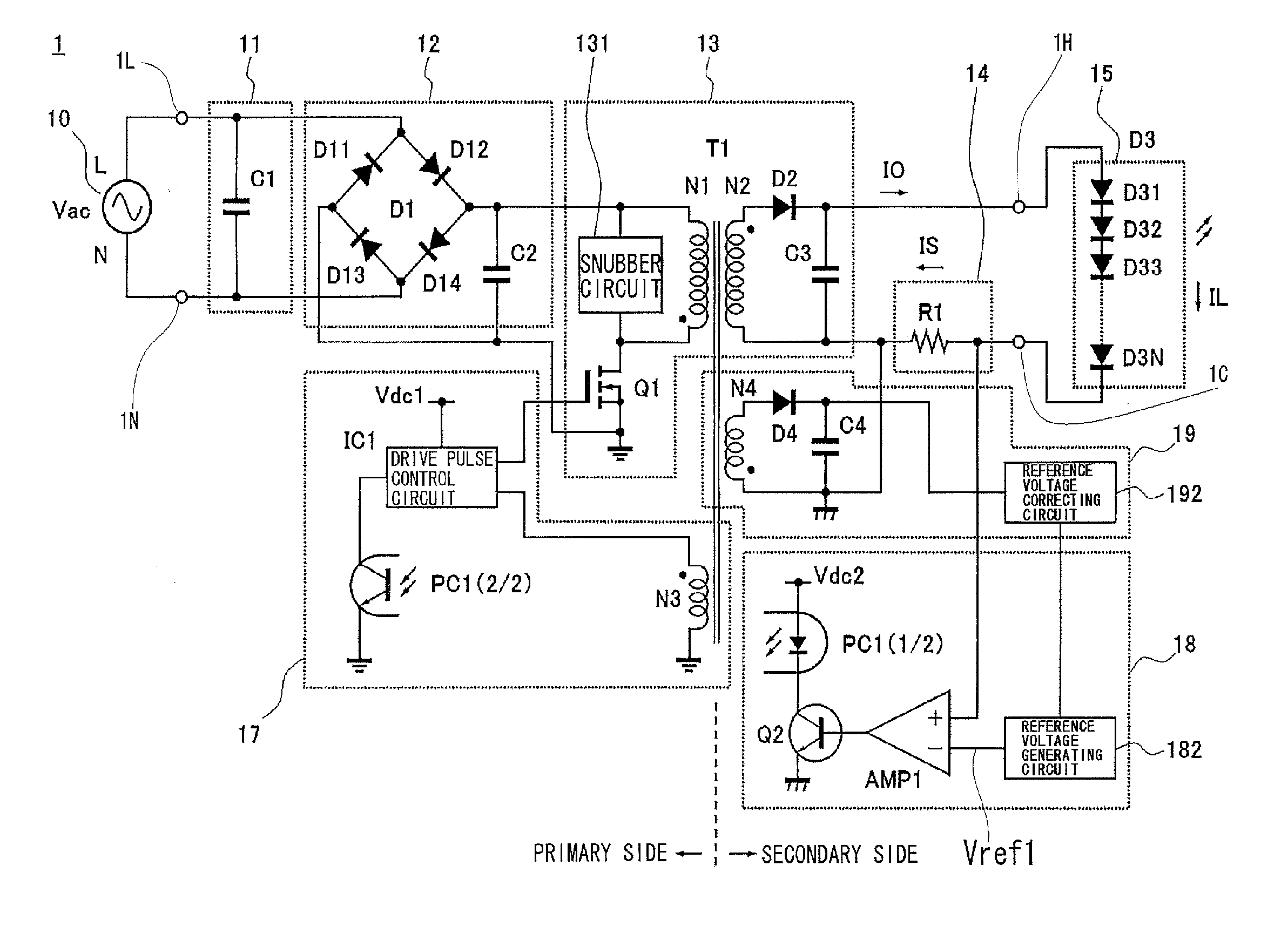
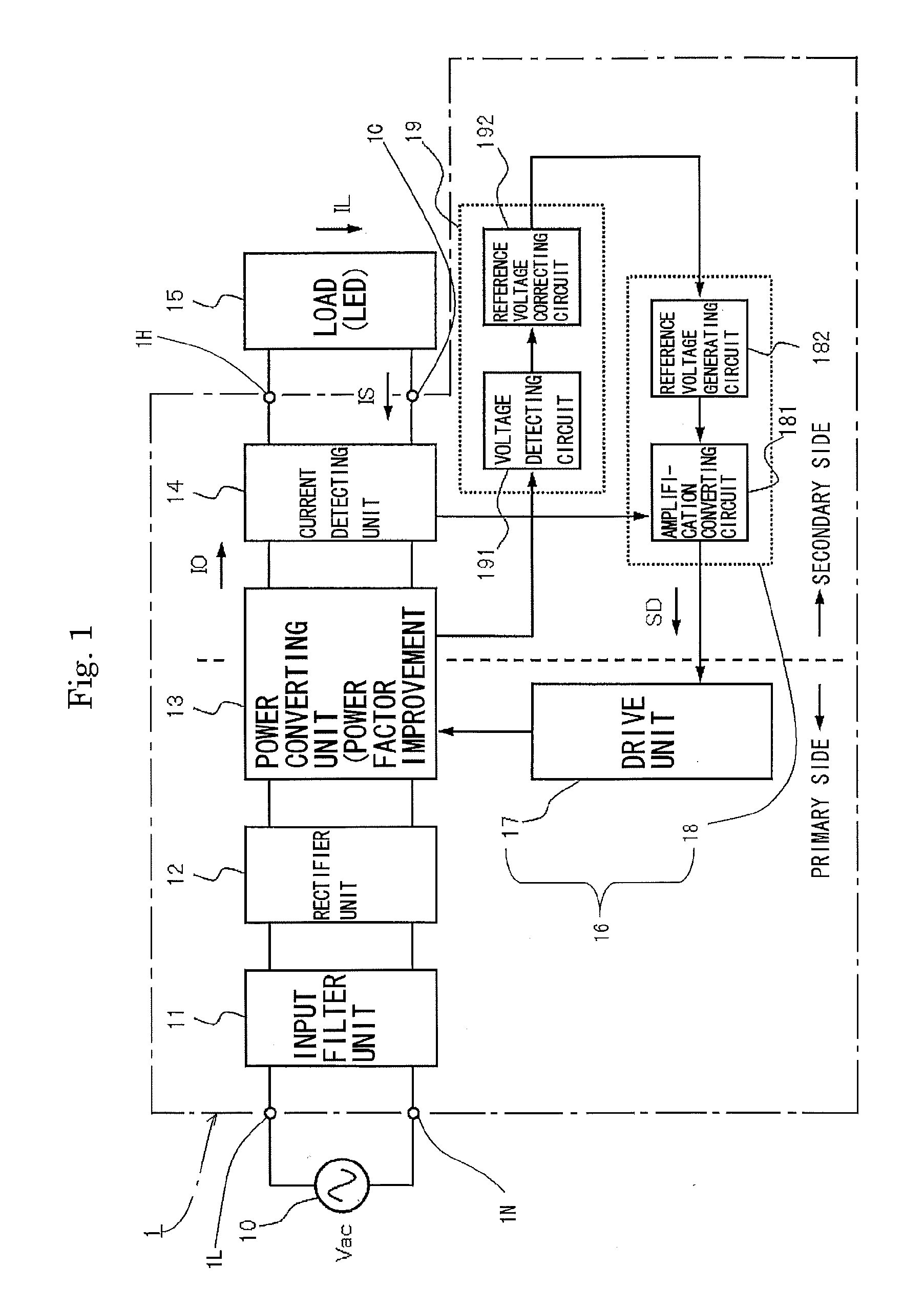
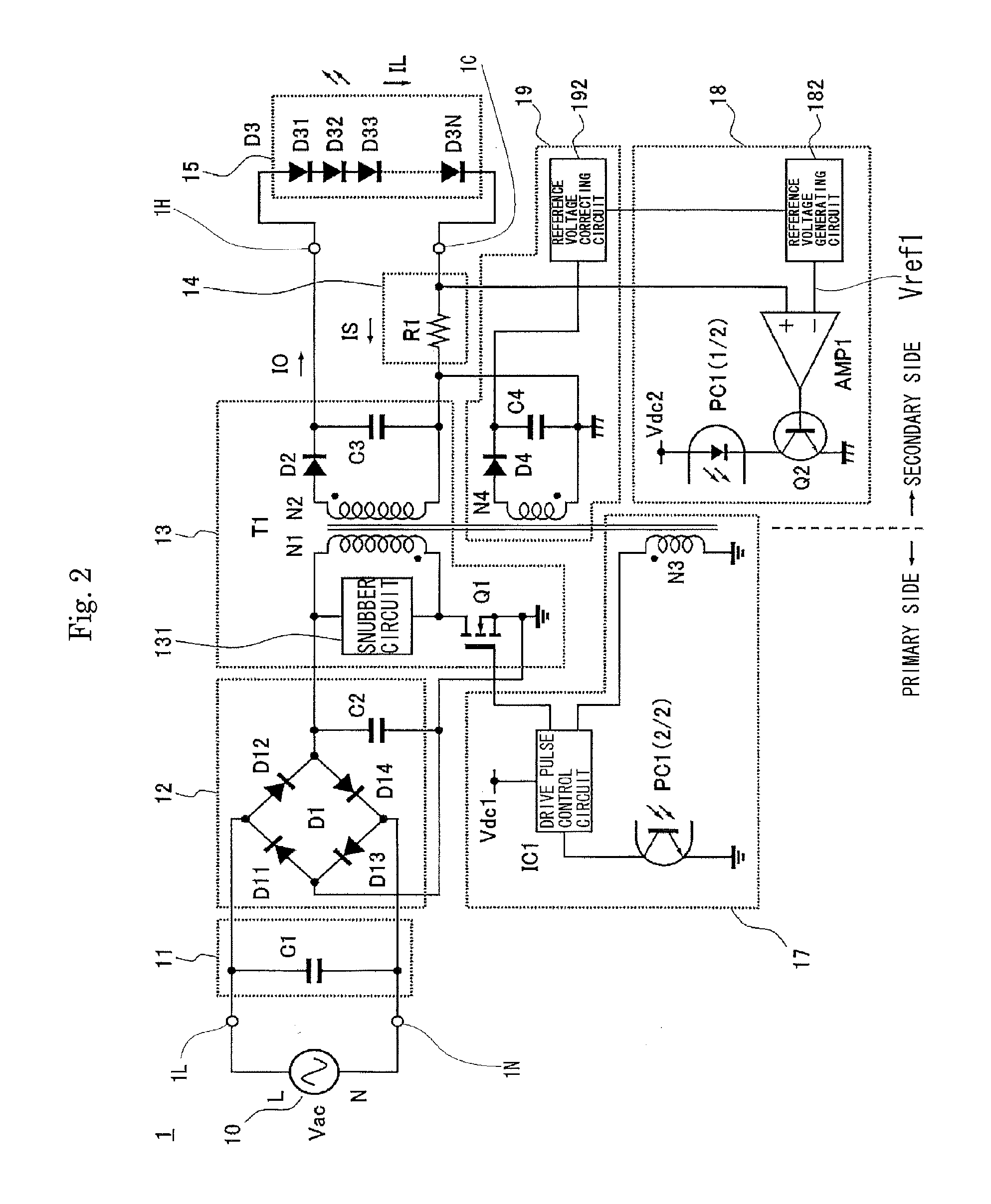
[0035]A switching power supply device according to the present invention will be described below with reference to the drawings. FIG. 1 is a schematic block diagram of a switching power supply device 1 according to the present invention; FIG. 2 is a view illustrating a schematic circuit configuration of the switching power supply device 1.

[0036]The switching power supply device 1 includes, as illustrated in FIGS. 1 and 2, an input filter unit 11, a rectifier unit 12, a power converting unit 13, a current detecting unit 14, a drive control unit 16 (including a drive unit 17 and a control unit 18), and an input voltage detecting unit 19. At input terminals 1L and 1N, electric power of voltage Vac is received from an AC power line 10 being a commercial power line; and load current IL is supplied to a load 15 (for example, a light-emitting diode (LED)). The control unit 18 includes an amplification converting circuit 181 and a reference voltage generating circuit 182; and the input volt...


PUM


Abstract

Implemented are a switching power supply device and a light-emitting diode lighting device in which a variation in load current can be suppressed against a wide range of variation in AC voltage. The configuration of the switching power supply device and the light-emitting diode lighting device includes: a rectifier unit which rectifies AC input voltage and outputs pulsating-current voltage; a power converting unit which receives the pulsating-current voltage and supplies a predetermined load current to a load; a current detecting unit which detects the load current; a drive control unit which controls the power converting unit to regulate the load current to a constant level; and an input voltage detecting unit which detects a variation in the AC input voltage. The drive control unit controls the power converting unit depending on the variation in the AC input voltage detected by the input voltage detecting unit.

Description

BACKGROUND OF THE INVENTION[0001]1. Field of the Invention[0002]The present invention relates to a switching power supply device used to drive a load (for example, light-emitting diode) by use of given current and to a light-emitting diode lighting device using the same, and more particularly to a switching power supply device and a light-emitting diode lighting device in which constant DC output current is provided against a wide range of variation in AC input voltage.[0003]2. Description of the Related Art[0004]In ordinary light emitting conditions, light-emitting diodes (hereinafter referred to as an LED) have current-voltage characteristics which have a small variation in forward voltage drop against a variation in drive current. Accordingly, LEDs are usually driven by a power supply device with constant current control. As such power supply device, a switching power supply device is usually used so that power consumption is reduced.[0005]As the switching power supply device wit...

Claims


Application Information

Patent Timeline
IPC IPC(8): H02M7/217H05B37/02
CPCH02M7/217H05B37/02Y02B20/346H02M2001/0025H05B33/0815H02M2001/0022H05B45/3725H05B45/385H05B47/10H02M1/0022H02M1/0025
Inventor SUZUKI, MASATAKANAKAMURA, YOSHIHIROKANAMITSU, HIDEHARUIMADA, HIROSHI
Owner MINEBEAMITSUMI INC
Why Eureka
Try Eureka