Mounting apparatus for memory card

a memory card and mounting apparatus technology, applied in the direction of coupling device connection, coupling/disassembly parts, instruments, etc., can solve the problems of only dissipating and blocking the airflow to the memory card

Inactive Publication Date: 2013-06-27
HONG FU JIN PRECISION IND (SHENZHEN) CO LTD +1
View PDF3 Cites 3 Cited by
  • Summary
  • Abstract
  • Description
  • Claims
  • Application Information

AI Technical Summary

Problems solved by technology

However, the fixing plates may block airflow to the memory card.
In a chassis having a plurality of memory cards arranged in para

Method used


Image

  • Mounting apparatus for memory card
  • Mounting apparatus for memory card
  • Mounting apparatus for memory card

Examples


Embodiment Construction

[0010]The disclosure, including the accompanying drawings in which like references indicate similar elements, is illustrated by way of examples and not by way of limitation. It should be noted that references to “an” or “one” embodiment in this disclosure are not necessarily to the same embodiment, and such references mean at least one.

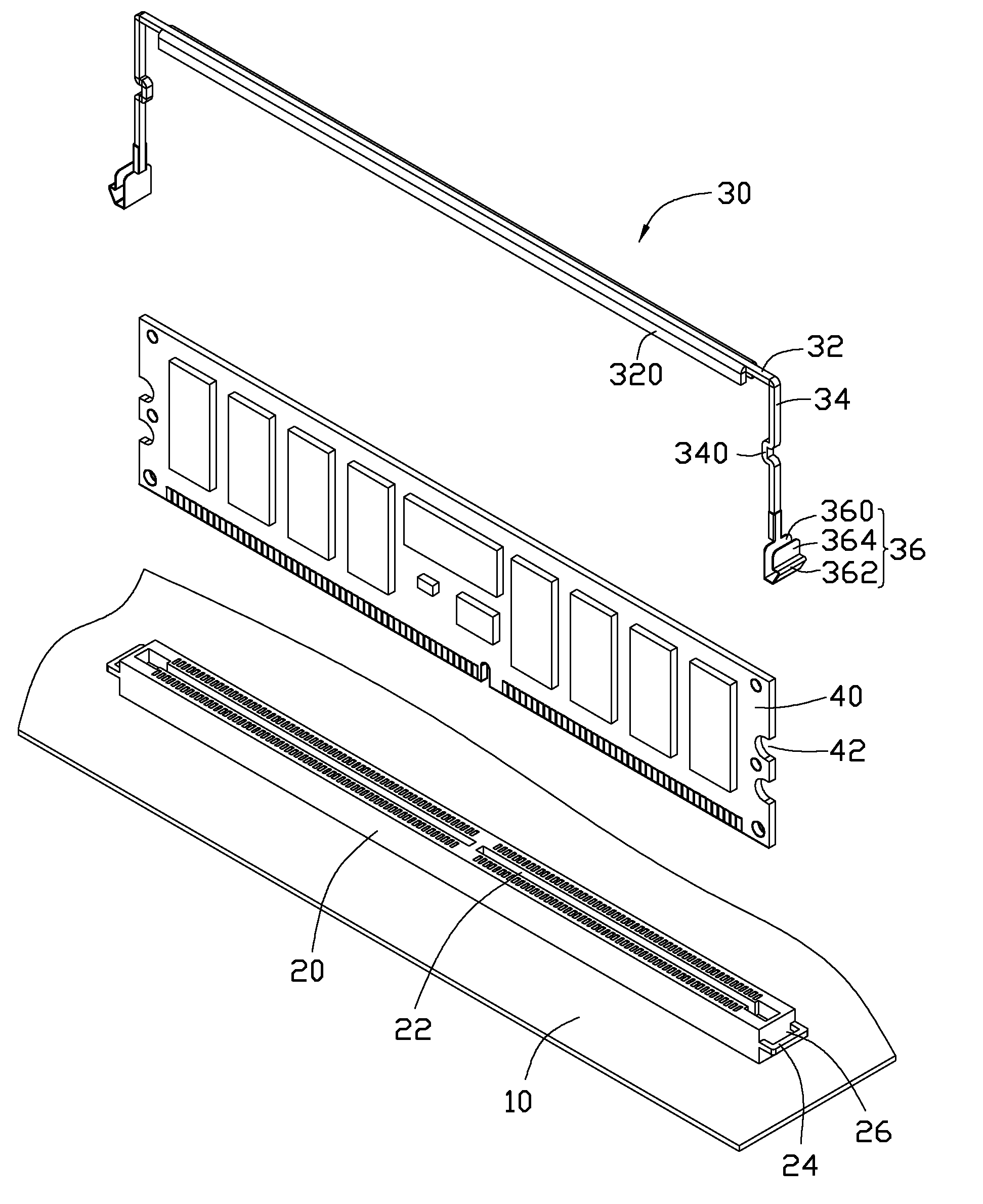
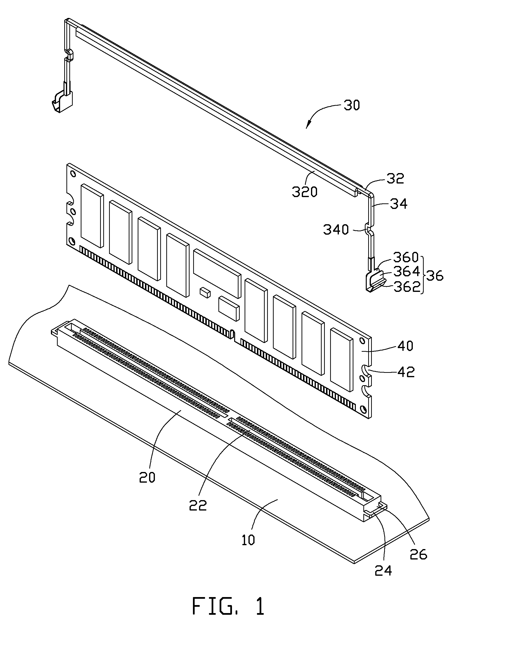
[0011]FIG. 1 is one embodiment of a mounting apparatus mounting a memory card 40 to a printed circuit board (PCB) 10. The mounting apparatus includes a connector 20 installed on the PCB 10, and a fixing member 30.

[0012]The memory card 40 defines a semicircular cutout 42 in each of opposite ends.

[0013]The connector 20 is elongated, and longitudinally defines a slot 22 in a top surface for electrically receiving the memory card 40. An ear 24 extends out from each of opposite end surfaces of the connector 20, and defines a through hole 26 extending through top and bottom of the ear 24.

[0014]The fixing member 30 includes a bar 32, two bar-shaped legs 34 p...


PUM


Abstract

A mounting apparatus for mounting a memory card to a printed circuit board (PCB) includes a connector mounted on the PCB and a fixing member. The connector defines a slot in a top surface for electrically receiving the memory card. An ear protrudes from each of opposite end surfaces of the connector and defines a through hole. The fixing member includes a bar abutted against a top of the memory, two legs respectively extending down from opposite ends of the bar to abut against opposite ends of the memory card, and two deformable latches respectively extending from distal ends of the legs and engaged in the corresponding through holes.

Description

BACKGROUND[0001]1. Technical Field[0002]The present disclosure relates to mounting apparatuses, and, particularly, to a mounting apparatus for a memory card.[0003]2. Description of Related Art[0004]A memory card is often installed in an electronic device, such as a computer or a server, using a mounting apparatus. The mounting apparatus includes two opposite fixing plates for clamping two opposite ends of the memory card. However, the fixing plates may block airflow to the memory card. In a chassis having a plurality of memory cards arranged in parallel, heat produced by the memory cards can only be dissipated through the narrow spaces between the cards, which is inefficient.BRIEF DESCRIPTION OF THE DRAWINGS[0005]Many aspects of the present embodiments can be better understood with reference to the following drawings. The components in the drawings are not necessarily drawn to scale, the emphasis instead being placed upon clearly illustrating the principles of the present embodiment...

Claims


Application Information

Patent Timeline
IPC IPC(8): H01R12/72
CPCG06F1/185
Inventor MA, XIAO-FENGSUN, ZHENG-HENG
Owner HONG FU JIN PRECISION IND (SHENZHEN) CO LTD
Why Eureka
Try Eureka