Dimming control system with distributed command processing

a control system and command processing technology, applied in the direction of electric variable regulation, process and machine control, instruments, etc., can solve the problems of significant complexity of the controller, and achieve the effect of increasing power control accuracy and high tolerance datum for board connector placemen

Inactive Publication Date: 2006-08-29
LEVITON MFG
View PDF14 Cites 3 Cited by
  • Summary
  • Abstract
  • Description
  • Claims
  • Application Information

AI Technical Summary

Benefits of technology

[0011]Dimmer Modules in the system incorporate a chassis engaged by the slot supports in the rack. A side load spring mounted on one side of the chassis urges the dimmer module against the opposite side wall of the rack thereby creating a high tolerance datum for board connector placement. A floating power connector is mounted in the chassis to receive the power bus blade. A full slot height lobed leaf spring for the side load spring prevents airflow in the rack slot outside the vented dimmer module itself and also provides secondary function as a ground contact. A three point keying system on the high tolerance wall of the rack prevents insertion of improperly rated dimmer modules in prewired slots.
[0012]Each dimmer module incorporates a power device having an on board microcontroller for dimming level control. Dimmer levels are provided as serial communication from the control modules in the rack to the dimmer module microcontroller, which provides local generation of PWM gating for SCR control in the power device. Internal intelligence in the dimmer module provided by the microcontroller allows individual dimmer control, diagnostics and calibration functions not possible in the prior art including module presence detection, type identification, load current sensing, open load sensing, circuit breaker open sensing, increased power control accuracy and individual temperature monitoring and control. In addition, panic switching is accomplished at each individual module through detection of DIP switches at each slot location by the microcontroller, independent of the presence or status of any control module in the rack.

Problems solved by technology

Consolidation of processing in a centralized controller for large numbers of dimmer control circuits creates significant complexity in the controller.

Method used


Image

  • Dimming control system with distributed command processing
  • Dimming control system with distributed command processing
  • Dimming control system with distributed command processing

Examples


Embodiment Construction

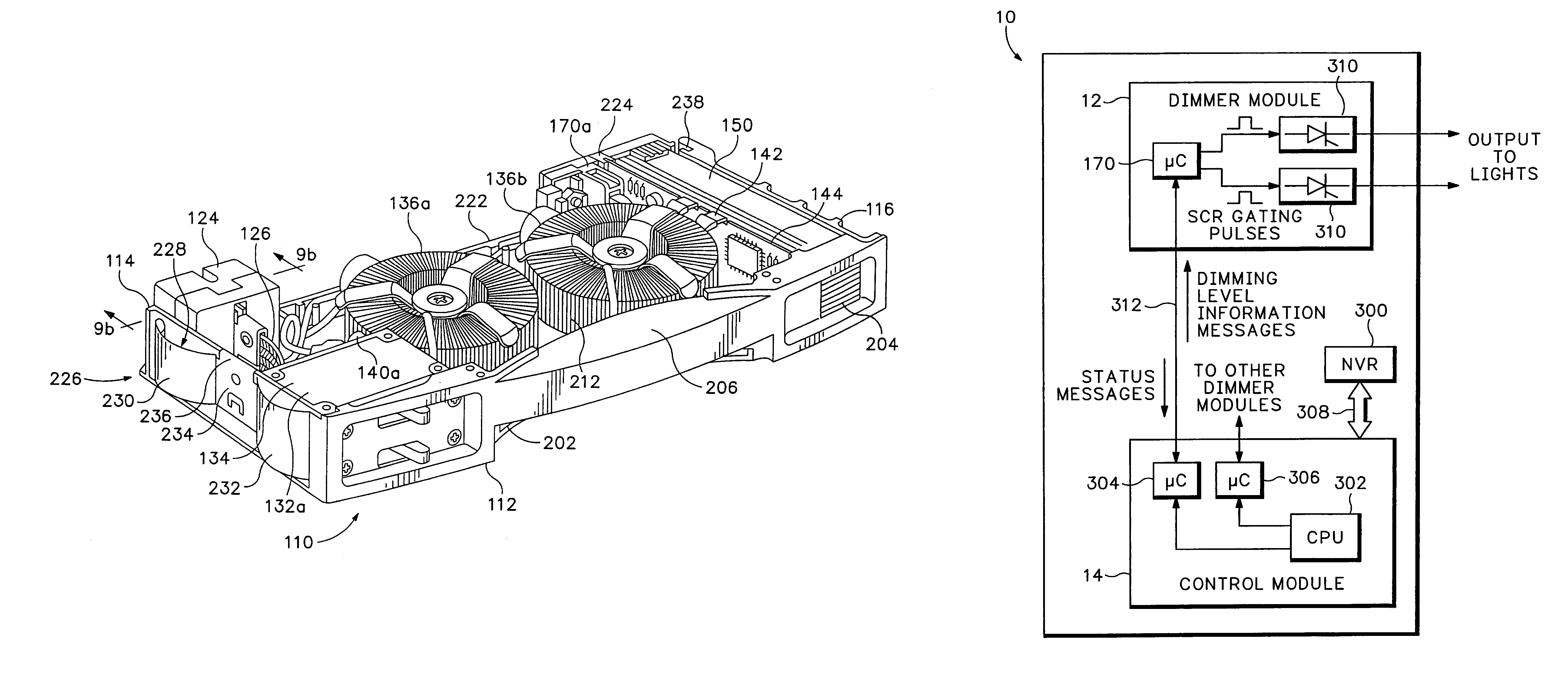
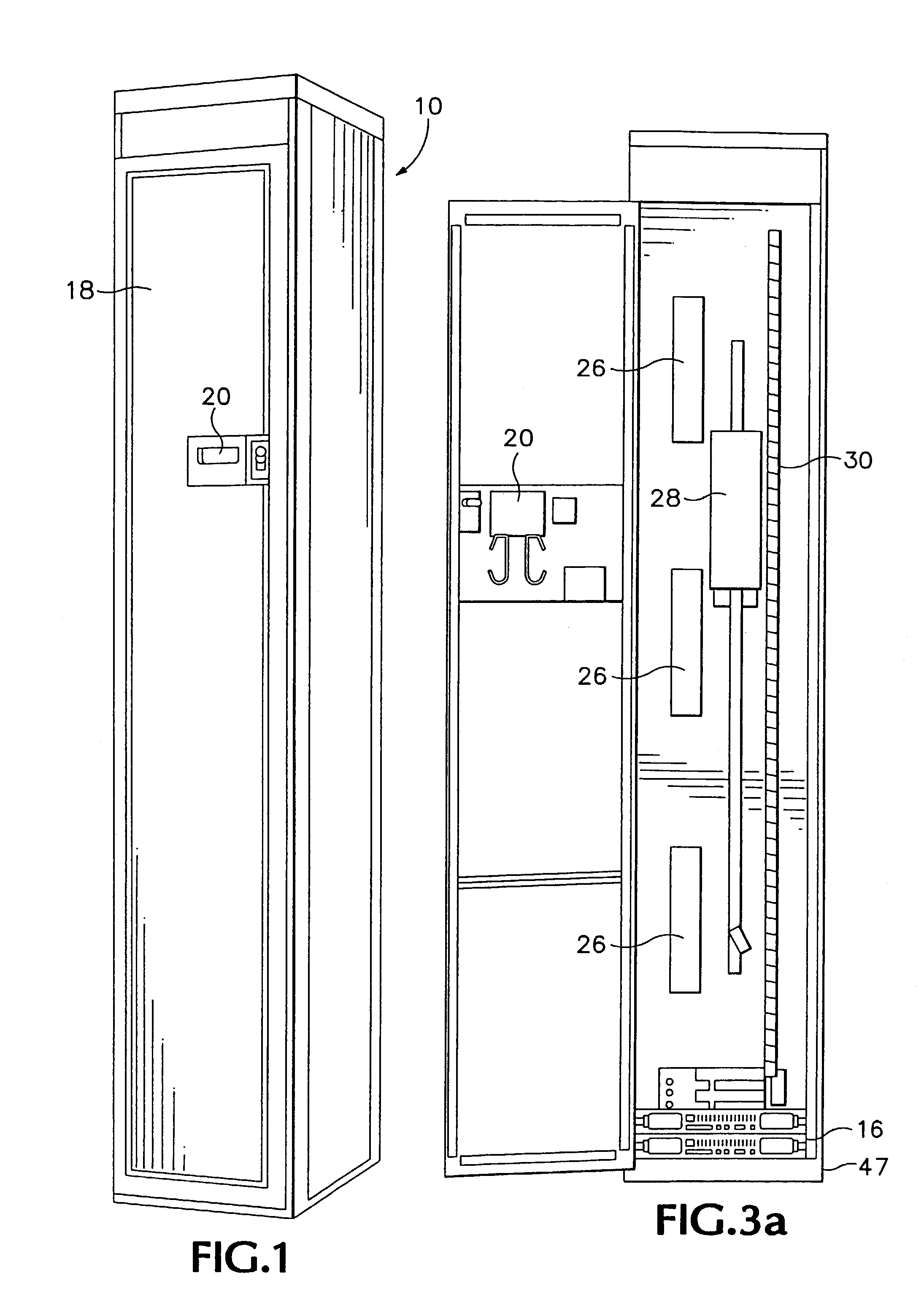
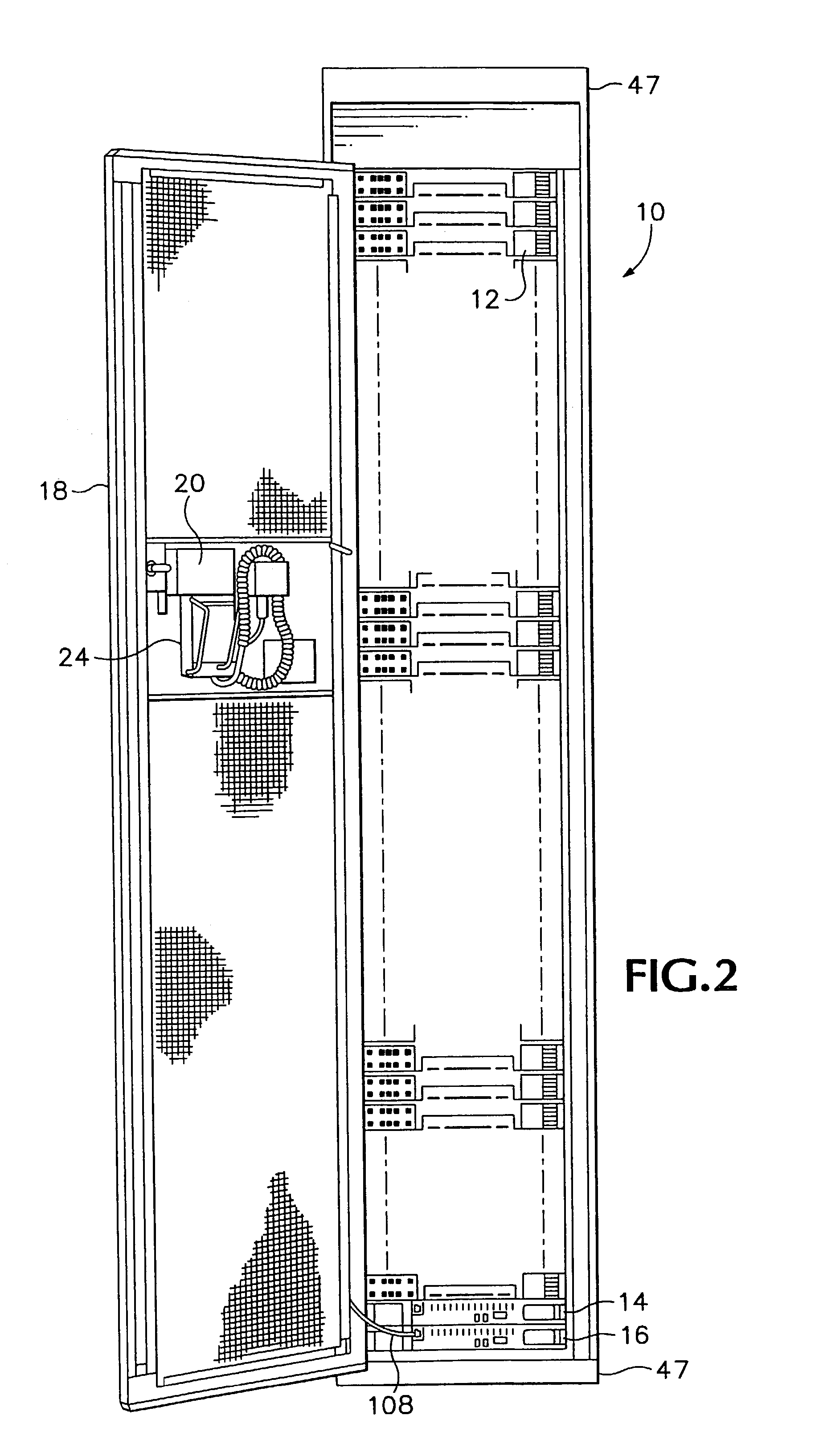
[0040]A dimming control system according to an embodiment of the invention is shown in FIGS. 1 and 2. The dimming rack 10 includes a structure having a plurality of integral supports to receive dimming modules 12 into a plurality of slots. Two control modules 14 are mounted in respective slots of a pull out tray 16 located in the bottom of the rack. A door 18 provides a closure for the rack and incorporates a viewing window 20 for the display of a hand held controller 22 held in a carrier 24 mounted to the interior of the door.

[0041]Details of the structural arrangement of the rack are best seen in FIGS. 3a–d shown with the dimmer modules removed from the rack. Power feed buses 26 each receiving power from one phase of a three phase supply are provided at three locations on the left side of the rack vertically spaced such that each blade of the power bus feed supplies one-third of the slots for dimmer modules. In alternative embodiments for single phase power applications, two power...


PUM


Abstract

A dimming control system includes dimmer modules that receive dimming level information from one of at least two control modules. Each dimmer module includes a microprocessor that provides internal intelligence for controlling power to a load in response to dimming level information. Control modules receive industry standard protocol dimming information from various sources, convert it to dimming level information, and serially communicate the dimming level information to the dimmer modules. Dimmer modules and control modules are mounted in a rack which includes a backplane having a nonvolatile memory device that retains configuration data even if control modules are removed from the rack. An inactive control module can assume control of the rack when an active control module fails.

Description

CROSS REFERENCE TO RELATED APPLICATIONS[0001]This application is a continuation of U.S. patent application Ser. No. 09 / 935,059, filed on Aug. 21, 2001 (now U.S. Pat. No. 6,603,276 B2), which is a divisional patent application of prior U.S. patent application Ser. No. 09 / 031,097 filed Feb. 26, 1998, (now U.S. Pat. No. 6,316,889 B1) which is a continuation of prior U.S. patent application Ser. No. 08 / 552,056 filed Nov. 2, 1995 (now U.S. Pat. No. 5,770,928).BACKGROUND OF THE INVENTION[0002]1. Technical Field of the Invention[0003]This disclosure relates to dimming control systems employing interchangeable dimmer modules and enclosures for mounting such dimmer modules and more particularly, to a unique dimmer module architecture employing on board intelligence for dimming control and a rack mounting system for the intelligent dimmer modules employing dual communications control modules for communication with individual dimmer modules in the rack and non-volatile memory in the rack backp...

Claims


Application Information

Patent Timeline
Patent Type & Authority Patents(United States)
IPC IPC(8): G05F1/00H05B37/02H05B39/08
CPCH05B37/0254H05B39/08H05B37/029Y10S315/04H05B47/155H05B47/18
Inventor CHANSKY, LEONARD M.VANNICE, KENLEVASSEUR, CRAIG
Owner LEVITON MFG
Why Eureka
Try Eureka