Vacuum regulator for maintaining a substantially constant vacuum in a vacuum system

a vacuum system and vacuum regulator technology, applied in the direction of fluid pressure control, process and machine control, instruments, etc., can solve the problems of difficult to establish a stable control of the airflow to the vacuum system, the valve body is opened, and the valve cone is set in a desired arbitrary position with high precision

Inactive Publication Date: 2004-08-10
DELAVAL HLDG AB
View PDF6 Cites 2 Cited by
  • Summary
  • Abstract
  • Description
  • Claims
  • Application Information

AI Technical Summary

Benefits of technology

This object is achieved in that the valve seat and the valve body have such design, that the value of said force increases, in a continuous way, with the degree of opening of the valve body. Thereby, it is possible to create a stable positioning of the valve body in a substantially arbitrary position. The quantity of air supplied to the vacuum system may be regulated with a high precision, which results in a stable and rapid control of the airflow to the vacuum system.
According to a preferred embodiment of the invention, the minimum flow area is determined by a part of the valve body. The active area of the valve body on which the vacuum acts is located at the minimum flow area of the passage. By a suitable design of the valve body and the valve seat, the active area is steadily located at said part of the valve body. Thereby, the active area is constant independent of the position of the valve body. Consequently, the active area of the valve body does not decrease with an increased degree of opening of the valve body, and the value of the force is not negatively influenced. Preferably, the largest radial cross section area of the valve body defines said part of the valve body. Thereby, a maximally active area of the valve body is utilised. Advantageously, said part of the valve body is arranged to be located radially inside the valve seat independent of the position of the valve body. Thereby, the valve seat has at least an extension corresponding to the distance between the closed and maximally open position of the valve body. By such a valve seat construction, the location of the minimum flow area to said part of the valve body is facilitated. Preferably, the size of the minimum flow area increases in a continuous way with the degree of opening of the valve body. Thereby, the airflow increases with the degree of opening of the valve body. The increased airflow results in an increased vacuum acting on the valve body. Thus, it is guaranteed that the value of the force acting on the valve body increases with the degree of opening of the valve body.
According to a further embodiment of the invention, the surface of the valve seat defines a tapering hole. Such a hole has an increased cross section area, in a continuous way, toward an inlet of the passage of valve seat. Consequently, the minimum flow area between the valve seat and valve body increases when the valve body moves towards an increased degree of opening. Advantageously, the valve body has a tapering shape. A tapered valve body provides a simple airtight connection to the valve seat. Furthermore, such a valve body provides a centering of the valve body in relation to the valve seat. The valve body may have a shape as a cone or a frustum of a cone. Preferably, the valve body is movable in an axial direction in relation to the valve seat. Thereby, the valve body is movable along a straight line, which facilitates the control of the valve body.
According to a further embodiment of the invention, such a control means may comprise a first diaphragm arranged between a first chamber connected to the atmospheric pressure and a second chamber connected to a control pressure. The diaphragm is moved against the second chamber if the control pressure is lower than the atmospheric pressure. The position of the diaphragm is related to the difference between the control pressure and the atmospheric pressure. The valve body obtains, by the connection to the diaphragm, a corresponding position by means of the control pressure. A pilot valve may be arranged to regulate the control pressure in the second chamber. Such a pilot valve may be connected to a second diaphragm arranged between a third chamber connected to atmospheric pressure and a fourth chamber connected to a signal pressure related to the actual vacuum in the vacuum system. If the actual vacuum in the vacuum system increases in relation to the desired vacuum, the diaphragm moves the pilot valve to a closed position. In the closed position, the pilot valve prevents an airflow to the second chamber. Since, for example, a small conduit connects the second chamber to the vacuum the control pressure in the second chamber is gradually reduced. The reduced control pressure results in an opening of the valve body and supply of air to the vacuum system. The supply of air to the vacuum system proceeds until the pressure in the vacuum system reaches the desired vacuum. When the desired vacuum is reached the pilot valve opens and air of atmospheric pressure is supplied to the second chamber and the valve body moves to the closed position. Preferably, the vacuum regulator comprises adjusting means arranged to enable adjustment of the desired vacuum level in the vacuum system. Such an adjusting means may comprise a compression spring, which is connected to the second diaphragm and arranged to compensate for the pressure difference between the third chamber having atmospheric pressure and the fourth chamber having the actual vacuum. The adjusting means may also comprise a tension mechanism arranged to adjust the prestressing of the spring. The adjusting means makes it is possible to adjust the vacuum in the vacuum system to a desired vacuum level.

Problems solved by technology

Thereby, it is difficult to set the valve cone in a desired arbitrary position with a high precision.
Consequently, it is difficult to establish a stable control of the airflow to the vacuum system.
The reduced control pressure results in an opening of the valve body and supply of air to the vacuum system.

Method used


Image

  • Vacuum regulator for maintaining a substantially constant vacuum in a vacuum system
  • Vacuum regulator for maintaining a substantially constant vacuum in a vacuum system
  • Vacuum regulator for maintaining a substantially constant vacuum in a vacuum system

Examples


Embodiment Construction

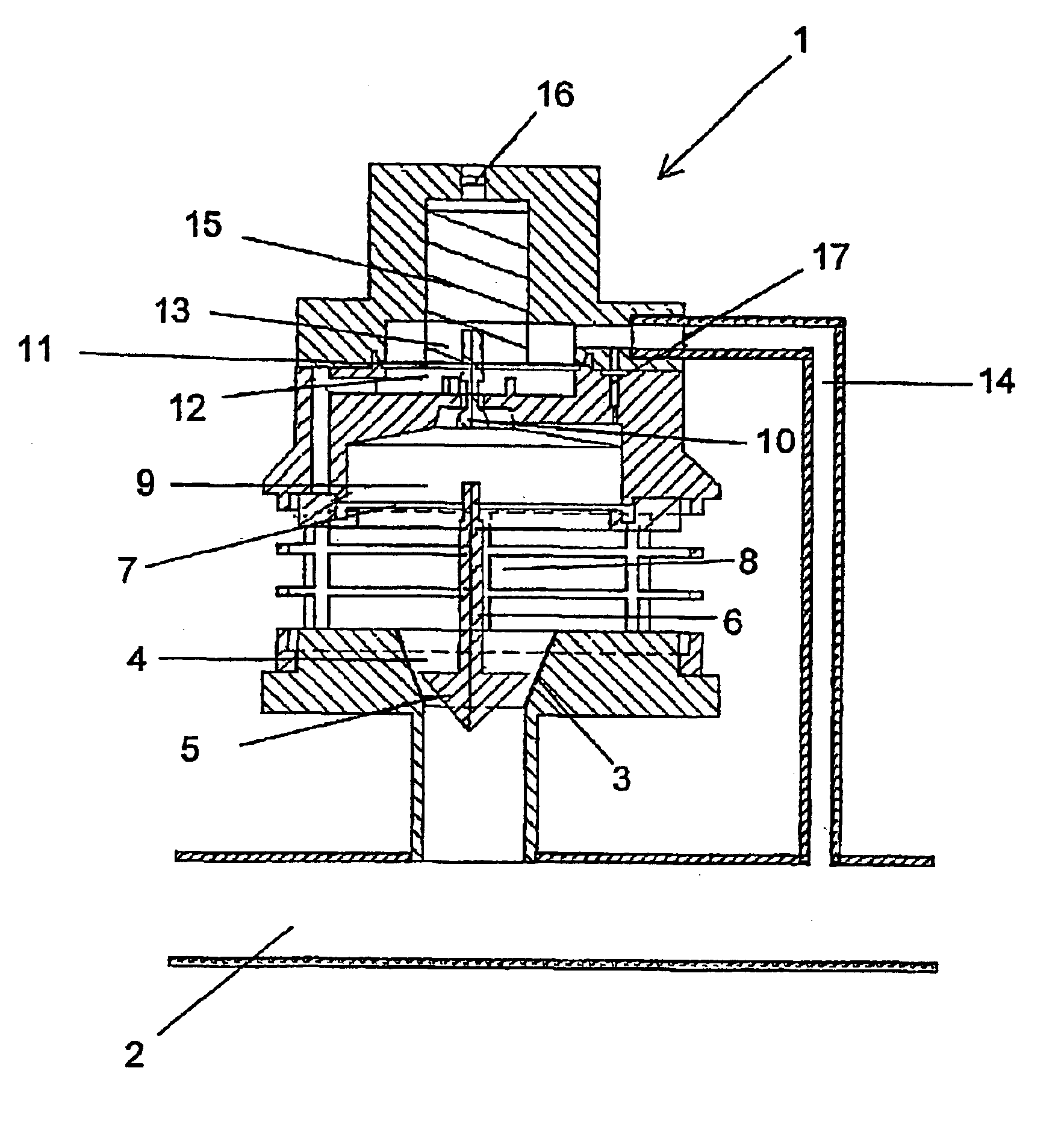
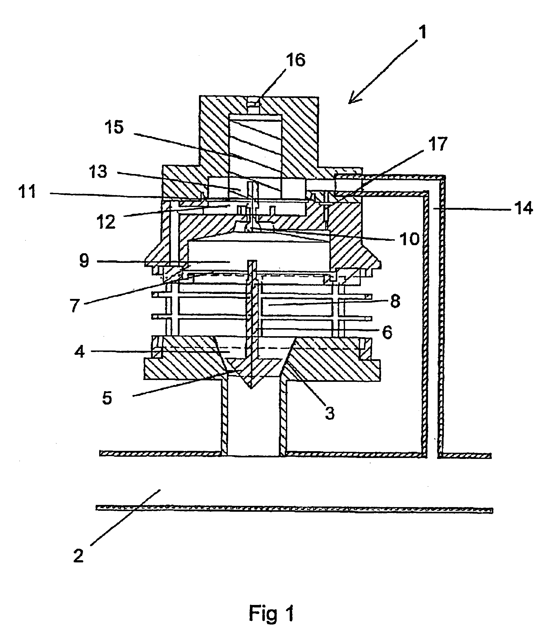
FIG. 1 shows a vacuum regulator 1. The vacuum regulator 1 is arranged to maintain a substantially constant vacuum level in a vacuum system comprising a vacuum pipe 2. Preferably, the vacuum in the vacuum pipe 2 is used in connection with a milking machine. In such vacuum systems, it is important to maintain a constant vacuum level. In order to remove the air leaking into the vacuum system, a vacuum pump is connected to the vacuum system. Such a vacuum pump must have capacity to maintain a higher vacuum in the vacuum system than the desired vacuum level The vacuum regulator 1 is connected to the vacuum system in order to supply air to the vacuum pipe 2 in such a quantity that the vacuum in the vacuum pipe 2 is maintained at the desired vacuum level.

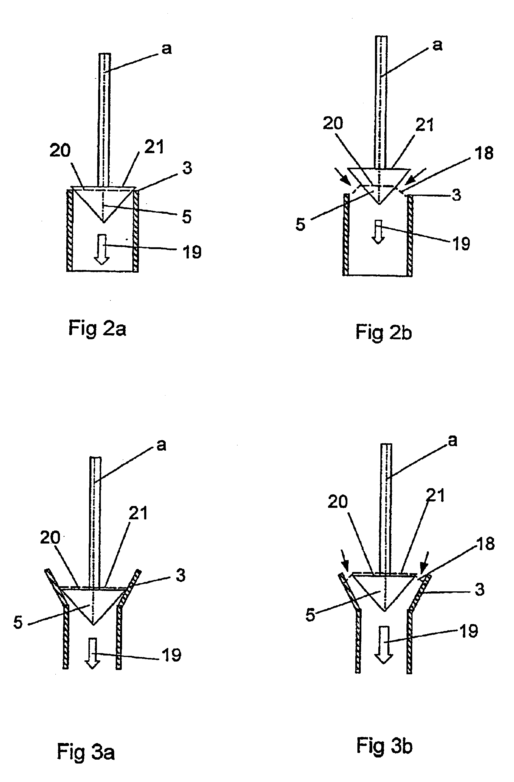
The vacuum regulator 1 comprises a main valve arranged to control the supply of air to the vacuum pipe 2. The main valve comprises a valve seat 3, having a surface defining a tapering hole 4 arranged to lead air to the vacuum pipe 2, and a...


PUM


Abstract

The invention relates to a vacuum regulator (1) for maintaining a substantially constant vacuum in a vacuum system (2). The vacuum regulator (1) includes a main valve arranged to control a supply of air to the vacuum system (2). The main valve includes a valve seat (3) defining a passage (4) arranged to lead air to the vacuum system (2) and a valve body (5) moveably arranged in a direction between a closed position and a maximally open position in order to regulate the size of a minimum flow area (18) between the valve seat (3) and the valve body (5). A force (19) caused by the vacuum acts on the valve body (5) in a direction towards the closed position. The valve seat (3) and the valve body (5) have such a design, that the value of the force (19), in a continuous way, increases with the degree of opening of the valve body (5).

Description

THE BACKGROUND OF THE INVENTION AND PRIOR ARTThe present invention relates to a vacuum regulator for maintaining a substantially constant vacuum in a vacuum system, wherein the vacuum regulator comprises a main valve arranged to control a supply of air to the vacuum system, wherein the main valve comprises a valve seat defining an passage arranged to lead air to the vacuum system and a valve body moveably arranged in a direction between a closed position and a maximally open position in order to regulate the size of a minimum flow area between the valve seat and the valve body and wherein a force caused by the vacuum acts on the valve body in a direction towards the closed positionIn vacuum systems used in connection with milking machines, it is important to maintain a desired constant vacuum in the vacuum system. In order to remove the air leaking into the system, a vacuum pump is connected to the vacuum system having a capacity to maintain more than the desired vacuum level in the...

Claims


Application Information

Patent Timeline
Patent Type & Authority Patents(United States)
IPC IPC(8): A01J5/04A01J5/00G05D16/16G05D16/00A01J7/00
CPCA01J5/048G05D16/163Y10S137/907G05D16/0638Y10T137/7835Y10T137/7762Y10T137/7764
Inventor IDENSJO, HENRIK
Owner DELAVAL HLDG AB
Why Eureka
Try Eureka