Fan

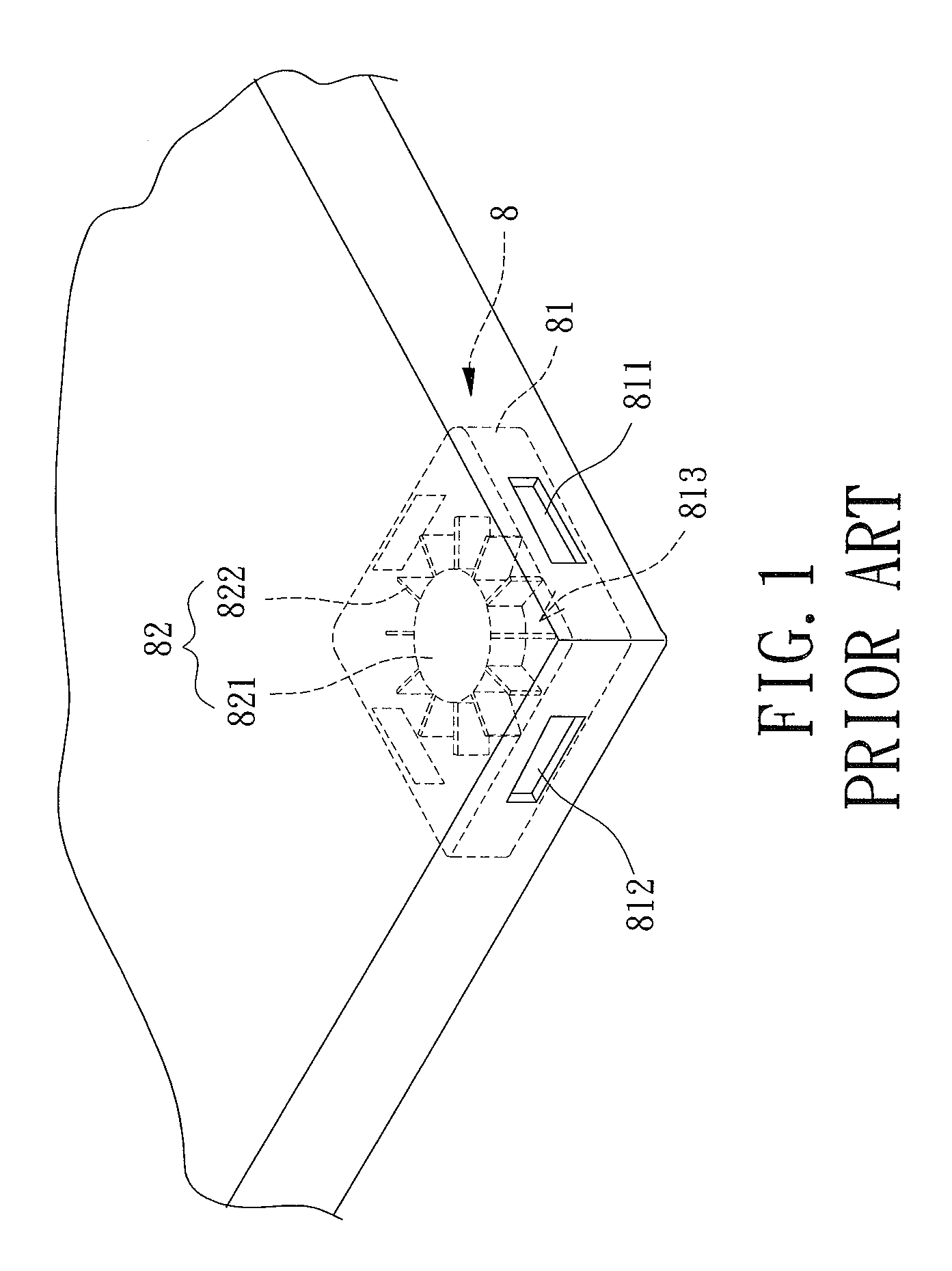
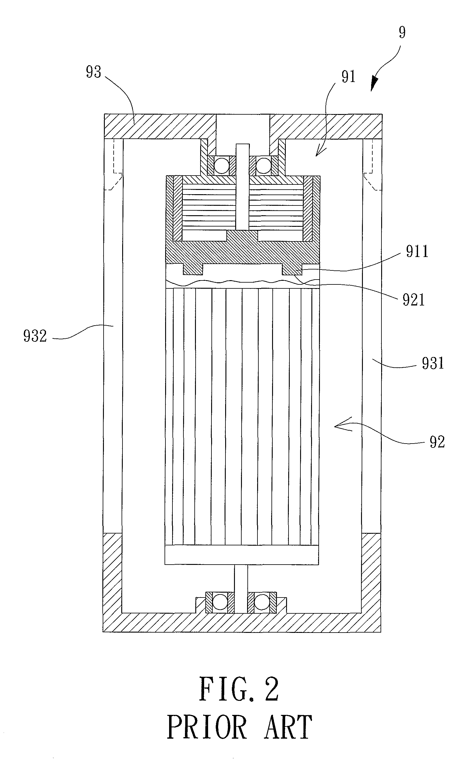
a technology of fan blades and fans, applied in the field of fans, can solve the problems of lowering the cooling efficiency of the conventional fan b>8/b>, and the inability to apply the blower type cooling fan to electronic devices, handsets or personal digital assistants, and achieve the effect of preventing airflow

Inactive Publication Date: 2015-03-10
SUNONWEALTH ELECTRIC MACHINE IND
View PDF8 Cites 2 Cited by
  • Summary
  • Abstract
  • Description
  • Claims
  • Application Information

AI Technical Summary

Benefits of technology

[0010]The primary objective of this invention is to provide a fan capable of preventing the airflow from being blocked by a hub of an impeller thereof when the impeller drives air in a radial direction.

Problems solved by technology

This is because the axial-flow type cooling fan can only expel air in the axial direction rather than the radial direction when performing the desired cooling operation.
In addition, since the blower type cooling fan draws air via the axial air inlet (in an axial direction) and expels air via the radial air outlet (in a radial direction), the blower type cooling fan cannot be applied to electronic devices that require drawing air from a lateral side thereof (from the radial direction), such as a handset or a Personal Digital Assistant (PDA).
Thus, turbulence is caused, and the cooling efficiency of the conventional fan 8 is therefore lowered.
However, it is troublesome to assemble the rotor seat 91 and the impeller 92.

Method used


Image

  • Fan
  • Fan
  • Fan

Examples


first embodiment

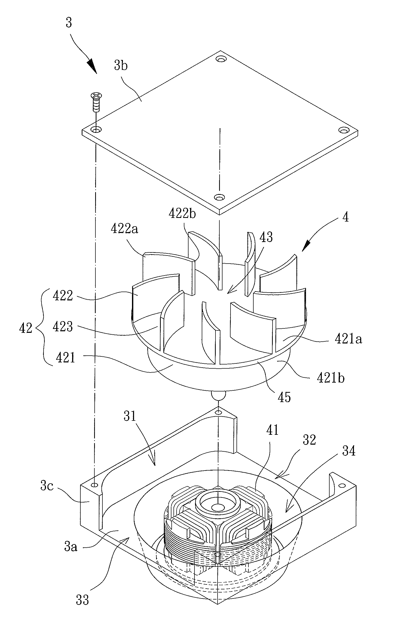
[0026]Referring to FIGS. 3 and 4, a fan comprising a housing 1 and a motor 2 is disclosed according to the invention. The housing 1 can receive the motor 2 and allow air to pass therethrough in a radial direction.

[0027]The housing 1 has closed top and bottom ends and comprises a support portion 1a, a cover portion 1b and a lateral wall portion 1c. The support portion 1a and the cover portion 1b are spaced from and opposite to each other, with the lateral wall portion 1c located between the support portion 1a and the cover portion 1b. The support portion 1a, cover portion 1b and lateral wall portion 1c jointly define a compartment 11. The lateral wall portion 1c has at least one lateral air inlet 12 and at least one lateral air outlet 13, with the at least one lateral air inlet 12 and the at least one lateral air outlet 13 communicating with the compartment 11.

[0028]In the embodiment, the support portion 1a is implemented as a base, and the lateral wall portion 1c is implemented as a...

second embodiment

[0038]Referring to FIG. 11, taking the fan of the second embodiment as an example, the lateral wall portion 3c can be integrally formed with the cover portion 3b.

[0039]In summary, based on the air-guiding room 23, 43 and the blades 222, 422 that extend from the top face 223 of the hub 221 towards the cover portion 1b, 3b, turbulence can be efficiently prevented to improve the cooling efficiency of the fan.


PUM


Abstract

A fan includes a housing and a motor. The housing has a compartment, at least one lateral air inlet and at least one lateral air outlet. The lateral air inlet and lateral air outlet communicate with the compartment. The motor has a stator and an impeller. The impeller is coupled with the stator and includes a hub and a plurality of blades coupled with a top face of the hub. Each blade has first and second ends. The first ends of the blades face outwards, and the second ends of the blades define an air-guiding room encompassed by a virtual geometric pattern formed by a virtual line linking the second ends of the blades. The virtual geometric pattern has a maximal diameter. A gap is formed between the second ends of two adjacent blades. The gap is smaller than the maximal diameter of the virtual geometric pattern.

Description

BACKGROUND OF THE INVENTION[0001]1. Field of the Invention[0002]The invention generally relates to a fan and, more particularly, to a fan that can drive air in a radial direction of an impeller thereof.[0003]2. Description of the Related Art[0004]Conventional cooling fans are mainly categorized into two types: an axial-flow type and a blower type. The axial-flow type cooling fan has an axial air inlet and an axial air outlet opposite to the axial air inlet. Air can be drawn via the axial air inlet and then expelled via the axial air outlet. The blower type cooling fan has an axial air inlet in the axial direction, as well as a radial air outlet in the radial direction thereof. Thus, air can be drawn via the axial air inlet and then expelled via the radial air outlet for a cooling operation.[0005]However, the axial-flow type cooling fan must be mounted on a top of an electronic device to be cooled, such as on the top of a Central Processing Unit (CPU) of a computer. This is because t...

Claims


Application Information

Patent Timeline
Patent Type & Authority Patents(United States)
IPC IPC(8): F04B35/04F04B17/00F04D29/44F04D29/54F04D17/04F04D25/06G06F1/20
CPCF04D25/0613F04D17/04G06F1/203
Inventor HORNG, ALEXWANG, KO-CHIEN
Owner SUNONWEALTH ELECTRIC MACHINE IND
Why Eureka
Try Eureka