

System and method for determining brake booster pressure
a technology of brake booster and pressure measurement, which is applied in the field of vehicle brake system, can solve the problems of increasing hardware complexity and increasing costs
- Summary
- Abstract
- Description
- Claims
- Application Information
AI Technical Summary
Benefits of technology
Problems solved by technology
Method used
Image

Examples
Embodiment Construction
[0014]The following description of the preferred embodiment(s) is merely exemplary in nature and is in no way intended to limit the invention, its application, or uses.
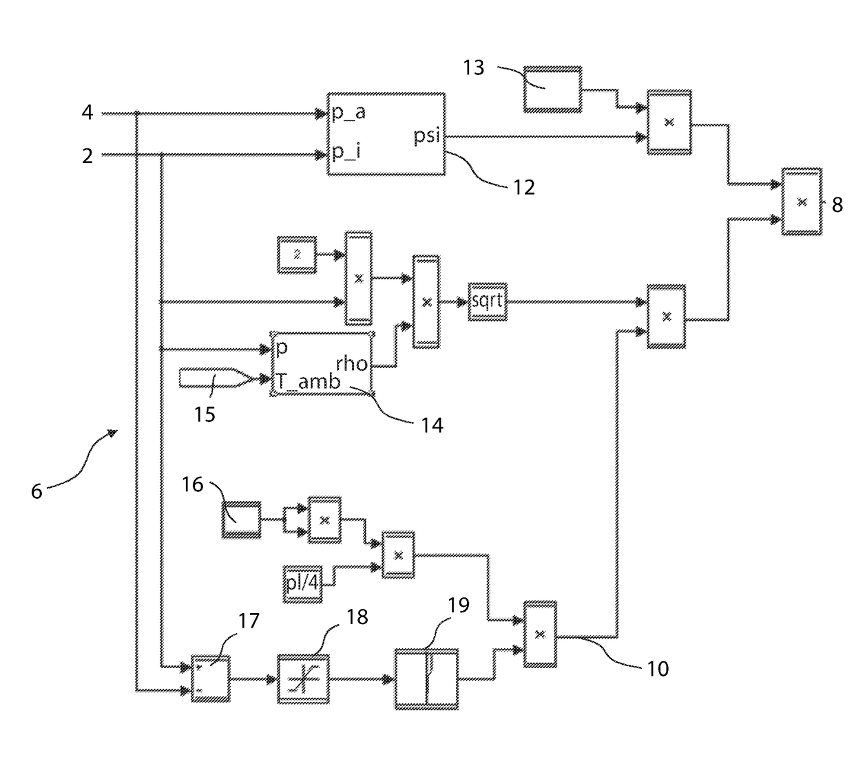
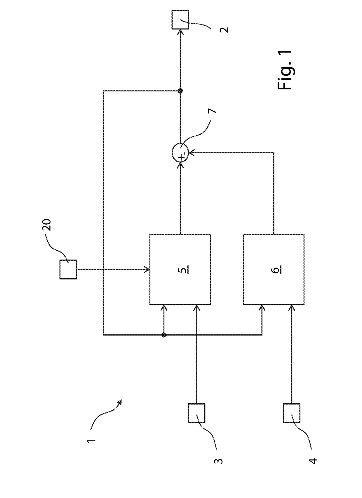
[0015]FIG. 1 is a schematic diagram of a system 1 for determining the pressure pbo(t) 2 in a brake booster (not shown) with reference to a hydraulic pressure 3 present in a main brake cylinder (not shown), an ambient pressure 20 present in the environment of the brake booster, and an intake manifold pressure 4 present in an intake manifold (not shown) according to one example of the present invention. The brake booster actuates a brake system (not shown) of a motor vehicle using the main brake cylinder. The brake booster connected in a fluid-conducting manner through a non-return valve to the intake manifold of an internal combustion engine of the motor vehicle. The non-return valve arranged and constructed to permit airflow from the brake booster to the intake manifold but to prevent airflow from the intake manifold ...
PUM
 Abstract
Description
Claims
Application Information