Electrical powered tail rotor of a helicopter

a technology of electric power and tail rotor, which is applied in the direction of machines/engines, magnetic circuit shapes/forms/construction, transportation and packaging, etc., can solve the problems of increasing rotor noise, introducing drag force, and adding weight, and achieves the effect of improving efficiency

Active Publication Date: 2013-07-04
AIRBUS HELICOPTERS DEUT GMBH
View PDF7 Cites 29 Cited by
  • Summary
  • Abstract
  • Description
  • Claims
  • Application Information

AI Technical Summary

Benefits of technology

[0016]It is an object of the invention to provide for an electri

Problems solved by technology

Tail rotors, while essential components, take power from the engi

Method used


Image

  • Electrical powered tail rotor of a helicopter
  • Electrical powered tail rotor of a helicopter
  • Electrical powered tail rotor of a helicopter

Examples


Embodiment Construction

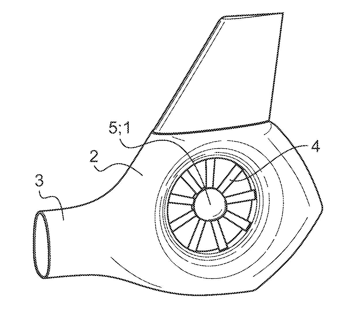
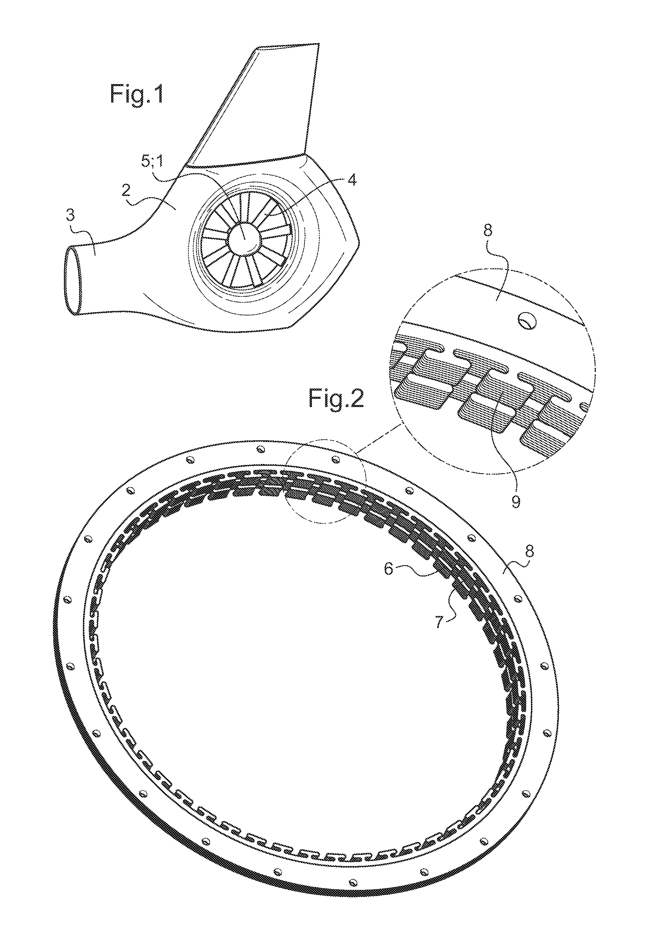
[0034]According to FIG. 1 a tail rotor 1 is arranged within a housing 2 of a helicopter's tail boom 3. Blades 4 of the tail rotor 1 are centrally supported by a hub 5. Hub 5 is essentially ball shaped towards an inlet side and essentially flat towards an outlet side of the tail rotor 1.

[0035]According to FIG. 2 two coaxial stators 6, 7 are provided on the inner circumference of a torus 8 of a brushless electrical motor assembly composed of two permanent magnet energized synchronous motors with a plurality of poles 9 on each of the two coaxial stators 6, 7.

[0036]The poles 9 on each of the two coaxial stators 6, 7 are connected to supply means (not shown) for electrical power. Power semiconductors (not shown) and microcontrollers (not shown) provide for two multiphase inverters (not shown) for precise control of the two brushless synchronous motors.

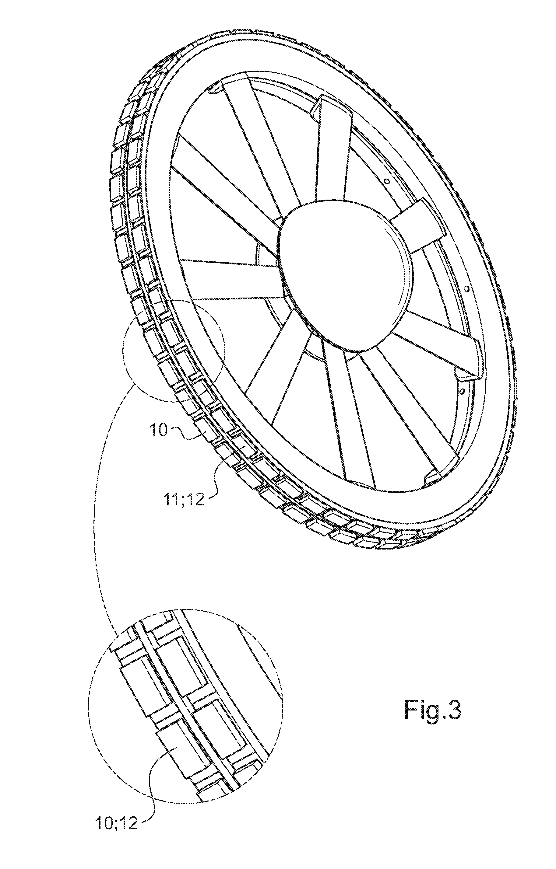
[0037]According to FIG. 3 the electrical motor assembly is composed of one rotating component 10, 11 for each of said two synchronous moto...


PUM


Abstract

The invention is related to an electrical powered tail rotor (1) of a helicopter comprising a housing (2) around the tail rotor (1), and at least one permanent magnet energized synchronous motor with a stator (6, 7) with an increased number of poles (9). Said at least one synchronous motor is integrated as a torus (8) around an opening of the housing (2) encompassing the tail rotor (1). Blades (4) of the tail rotor (1) are fixed to at least one rotating component (10, 11) of said at least one synchronous motor. Supply means provide for electric energy to said at least one synchronous motor. Blade pitch control means are provided at the torus (8).

Description

CROSS REFERENCE TO RELATED APPLICATIONS[0001]This application claims priority to European patent application No. 11 400062.3 filed Dec. 28, 2011, the disclosure of which is incorporated in its entirety by reference herein.BACKGROUND OF THE INVENTION[0002](1) Field of the Invention[0003]The invention is related to an electrical powered tail rotor of a helicopter with the features of the preamble of claim 1.[0004](2) Description of Related Art[0005]The power consumed by a tail rotor of state of the art helicopters is supplied from a central energy generator via a main gear box, a plurality of intermediate gears and a tail rotor shaft. By removing the main gear box and the rigid mechanical coupling between energy generator and tail rotor more design flexibility for the helicopter may be attained. One of the keys to realise an electrical powered tail rotor of a helicopter is a suitable electrical motor.[0006]The document US 2004051401 A1 discloses an electric motor for rotating an objec...

Claims


Application Information

Patent Timeline
IPC IPC(8): B64C27/12
CPCB64C27/82H02K7/116H02K7/14B64C27/12B64C2027/8209B64C2027/8254H02K16/00H02K1/17
Inventor ALTMIKUS, ANDREEKESSLER, MANUEL
Owner AIRBUS HELICOPTERS DEUT GMBH
Why Eureka
Try Eureka