Vehicle door trim

a technology for vehicles and doors, applied in the field of vehicles and doors, can solve the problems of higher load until the leg is buckled than expected, and achieve the effects of preventing deformation of the trim main body, reducing the buckling load of the rising wall portion of the clip, and reducing the collision reaction force of the clip installation bas

Active Publication Date: 2013-07-18
TOYOTA JIDOSHA KK
View PDF9 Cites 15 Cited by
  • Summary
  • Abstract
  • Description
  • Claims
  • Application Information

AI Technical Summary

Benefits of technology

[0013]Therefore, according to the invention, the clip rising wall portion includes the bent portion. Even if the impact load is input to the clip installation base, the collision reaction force by the clip installation base is reduced because the bent portion has no force application point. Furthermore, when the collision load is input to the clip installation base, stress is concentrated at the bent portion. Consequently, the clip rising wall portion becomes easy to deform by buckling. Compared to a case where the clip rising wall portion is provided substantially in parallel to a load direction, the buckling load of the clip rising wall portion is reduced, so that rise-up of the collision reaction force at an initial period by the clip rising wall portion is reduced.
[0014]In the meantime, if the clip rising wall portion is deformed by buckling by the impact load input to the clip installation base so that it is bent inward of the closed sectional area, the clip rising wall portion comes to be arranged like in a state in which two portions thereof are stacked between the trim main body and the clip settling portion. Thus, an impact stroke of the clip rising wall portion is reduced by an amount corresponding to a thickness of the two portions of the clip rising wall portion, thereby preventing deformation of the trim main body and resulting in quick bottoming of the deformation.
[0015]However, because according to the invention, the bent portion of the clip rising wall portion has an angle so as to be convex outward of the closed section portion of the clip installation base, when the clip rising wall portion is deformed by buckling by the impact load, the clip rising wall portion is bent outward of the closed section portion. Consequently, between the trim main body and the clip settling portion, an impact stroke, which is set at design stage, can be secured. That is, when the bent portion of the clip rising wall portion is provided, a starting point of bending of the clip rising wall portion is provided, which stabilizes buckling deformation mode. The buckling load of the clip rising wall portion can be adjusted easily by the angle of the bent portion. Therefore, the invention has an excellent advantage that a collision reaction force that a passenger receives when he or she collides secondarily with the door trim upon a side collision can be damped efficiently.

Problems solved by technology

However, because according to the related art, the leg portion of the clip installation base is formed in parallel to an input direction of a side collision load, there is a possibility that the load until the leg is buckled may be higher than expected.

Method used


Image

  • Vehicle door trim
  • Vehicle door trim
  • Vehicle door trim

Examples


Embodiment Construction

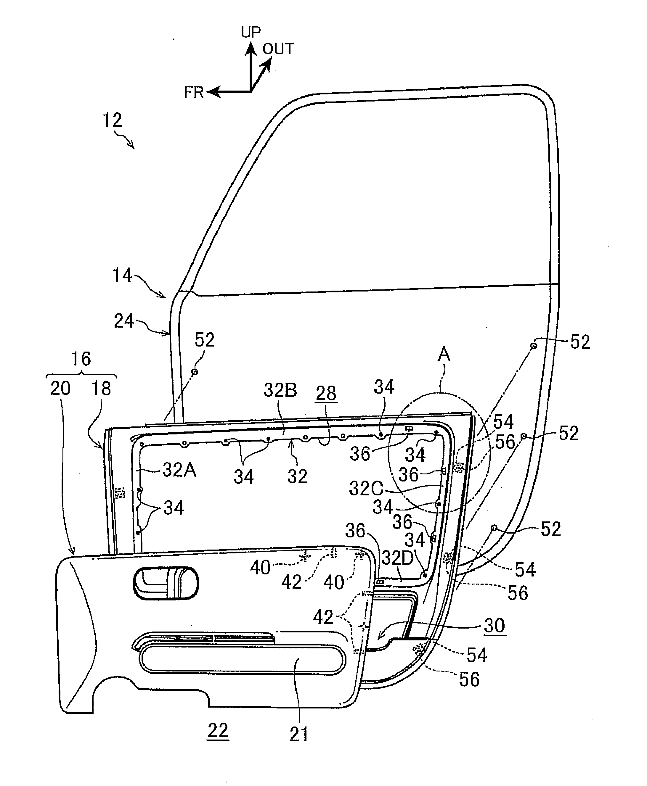
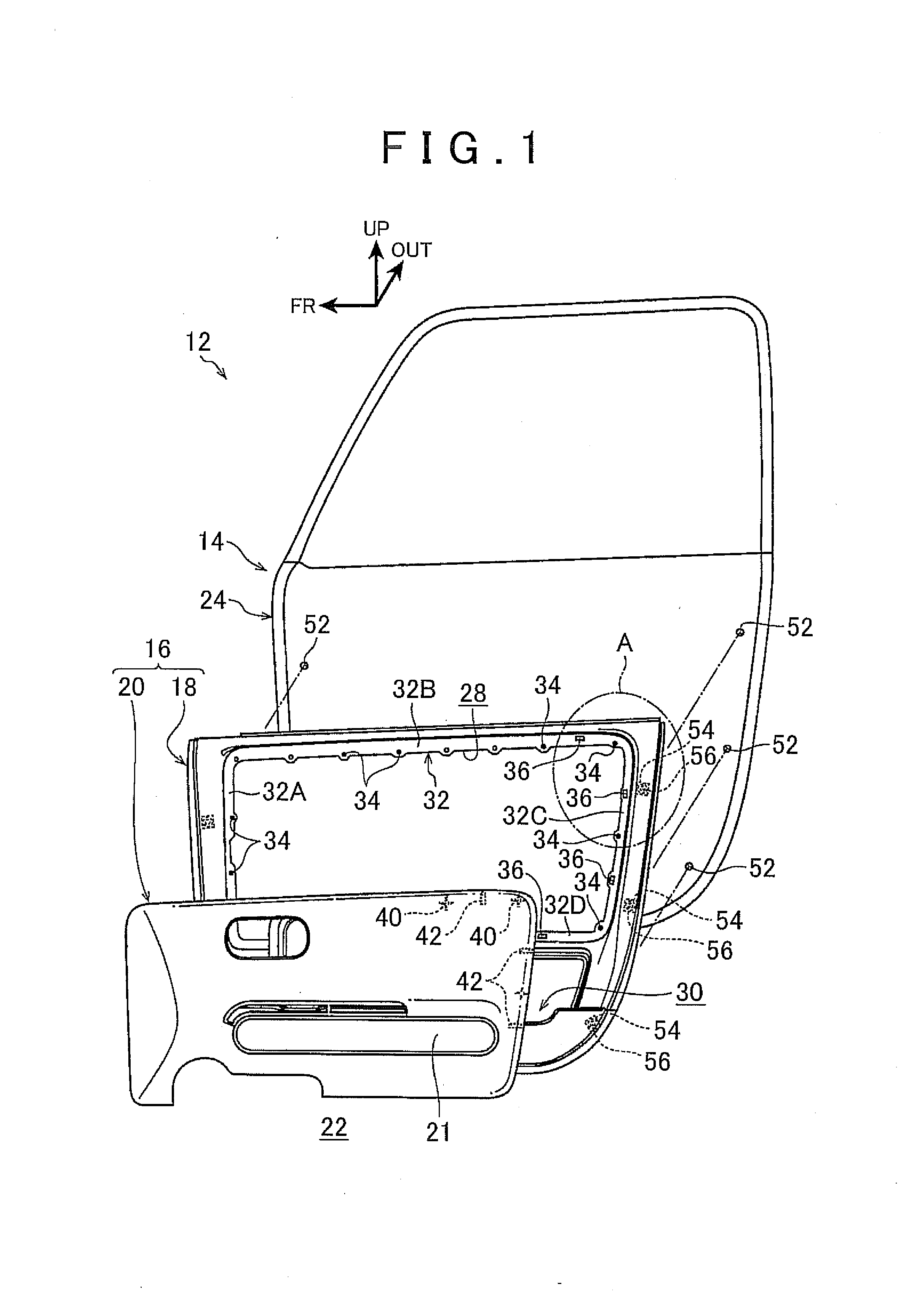
[0029]Hereinafter, an embodiment of the invention will be described with reference to the accompanying drawings. An arrow FR in the figures indicates forward in the longitudinal direction of a vehicle, an arrow UP indicates upward in the vertical direction of the vehicle and an arrow OUT indicates outward in the vehicle width direction.

(Configuration of Installation Structure of Vehicle Door Trim)

[0030]FIG. 1 shows an exploded side view of a side door 12 of a passenger vehicle to which an installation structure of a vehicle door trim of the present embodiment is applied, the side door 12 including a door panel 14 and a door trim 16 (base panel 18 and decorative panel 20) that is a trim main body when viewed from the interior side of a vehicle compartment 22. FIG. 2 shows a front view of the door trim 16 in which the decorative panel 20 is installed on a central portion of the base panel 18 occupying an outer periphery of the door trim 16.

[0031]As shown in these figures, the door pan...


PUM

PropertyMeasurementUnit
angleaaaaaaaaaa
angleaaaaaaaaaa
angleaaaaaaaaaa

Abstract

A door trim for a vehicle includes: a trim main body formed so as to be bulging out inward of a vehicle compartment as an interior furnishing material of a door inner panel of a side door; and a clip installation base provided on the trim main body in a rear side area thereof with respect to the vehicle. The clip installation base includes: a clip settling portion configured to be opposed to the door inner panel and to be fitted with a clip to be mounted in a mounting hole formed in the door inner panel; and a clip rising wall portion provided continuously with the clip settling portion and forming a closed section portion together with the trim main body and the clip settling portion in a horizontal section, the clip rising wall portion including a bent portion having an angle so as to be convex outward.

Description

INCORPORATION BY REFERENCE[0001]The disclosure of Japanese Patent Application No. 2012-004127 filed on Jan. 12, 2012 including the specification, drawings and abstract is incorporated herein by reference in its entirety.BACKGROUND OF THE INVENTION[0002]1. Field of the Invention[0003]The invention relates to a vehicle door trim, and more particularly to an installation structure thereof.[0004]2. Description of Related Art[0005]According to a door trim installation structure described in Japanese Patent Application Publication No. 2011-126489 (JP 2011-126489 A), a clip installation base on which a clip to be mounted to a door inner panel is installed are arranged such that it is spanned between a rising wall portion (trim rising wall portion) of a trim main body and an ornament portion (trim general portion). At a leg portion of the clip installation base provided continuously with the ornament portion, rigidity of an upper side thereof is set higher than that of a lower side.[0006]Ac...

Claims


Application Information

Patent Timeline
Patent Type & Authority Applications(United States)
IPC IPC(8): B60J5/04
CPCB60J5/0413B60R13/0243Y10T29/49826
Inventor TORII, NOBUYUKI
Owner TOYOTA JIDOSHA KK
Why Eureka
Try Eureka