Spine surgery method and implant

a technology of spine surgery and implant, applied in the field of spine surgery, can solve the problems of reducing surgeon visualization of the surgical site, physical components are relatively large and bulky, and the known spinal surgical method, and achieve the effects of maximizing boney ingrowth surface area and bone graft-host contact, minimally invasive deployment, and enhancing bone graft-vertebral visualization

Active Publication Date: 2013-11-21
FABIAN HENRY F +1
View PDF27 Cites 126 Cited by
  • Summary
  • Abstract
  • Description
  • Claims
  • Application Information

AI Technical Summary

Benefits of technology

[0019]According to another aspect of this invention, if necessary, the pin can be sheared to unlock the locking mechanism. In one embodiment, the pin has a channel permitting the pin to be sheared at the interface of the first beam of the first member and the first beam of the second member. With this arrangement, both portions of the sheared pin remain confined within the implant and thus will not be inadvertently left within the intradiscal space.
[0020]One advantage of this invention is that the implant has an open profile when fully expanded, maxi

Problems solved by technology

As a result, known spinal surgical methods, instrumentation and interbody implants have disadvantages.
One disadvantage is that the physical components are relatively large and bulky.
This reduces surgeon visualization of the surgical site.
Another disadvantage of know spinal surgical methods is that known surgical tools and implants are cumbersome and difficult to maneuver within the limited surgical space available.
Despite this progression in intradiscal implant geometry, a device havin

Method used


Image

  • Spine surgery method and implant
  • Spine surgery method and implant
  • Spine surgery method and implant

Examples


Embodiment Construction

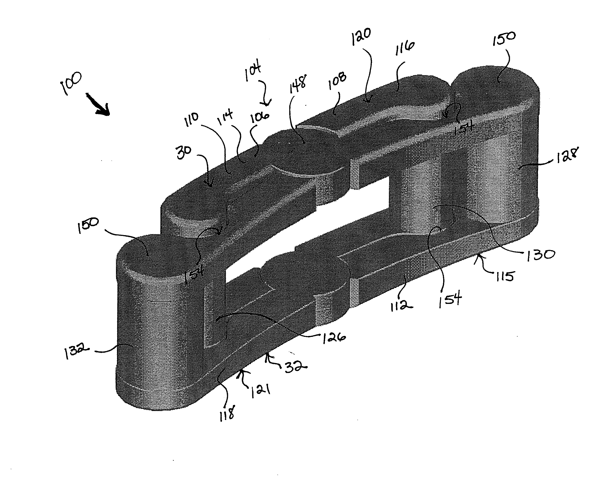
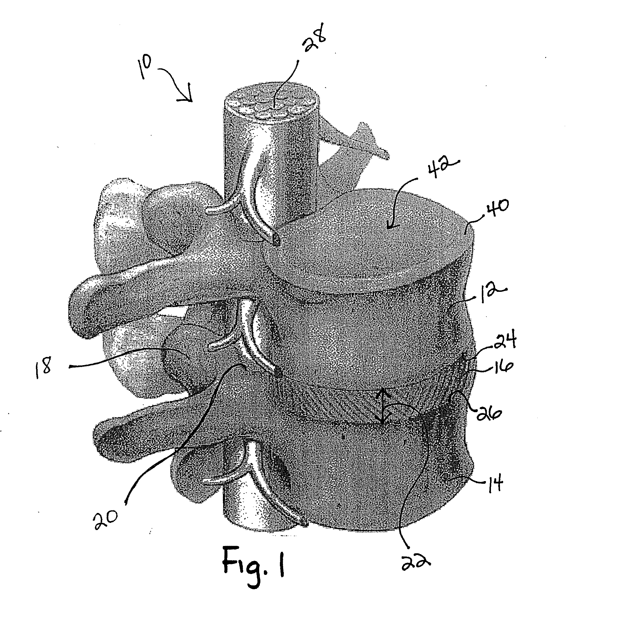
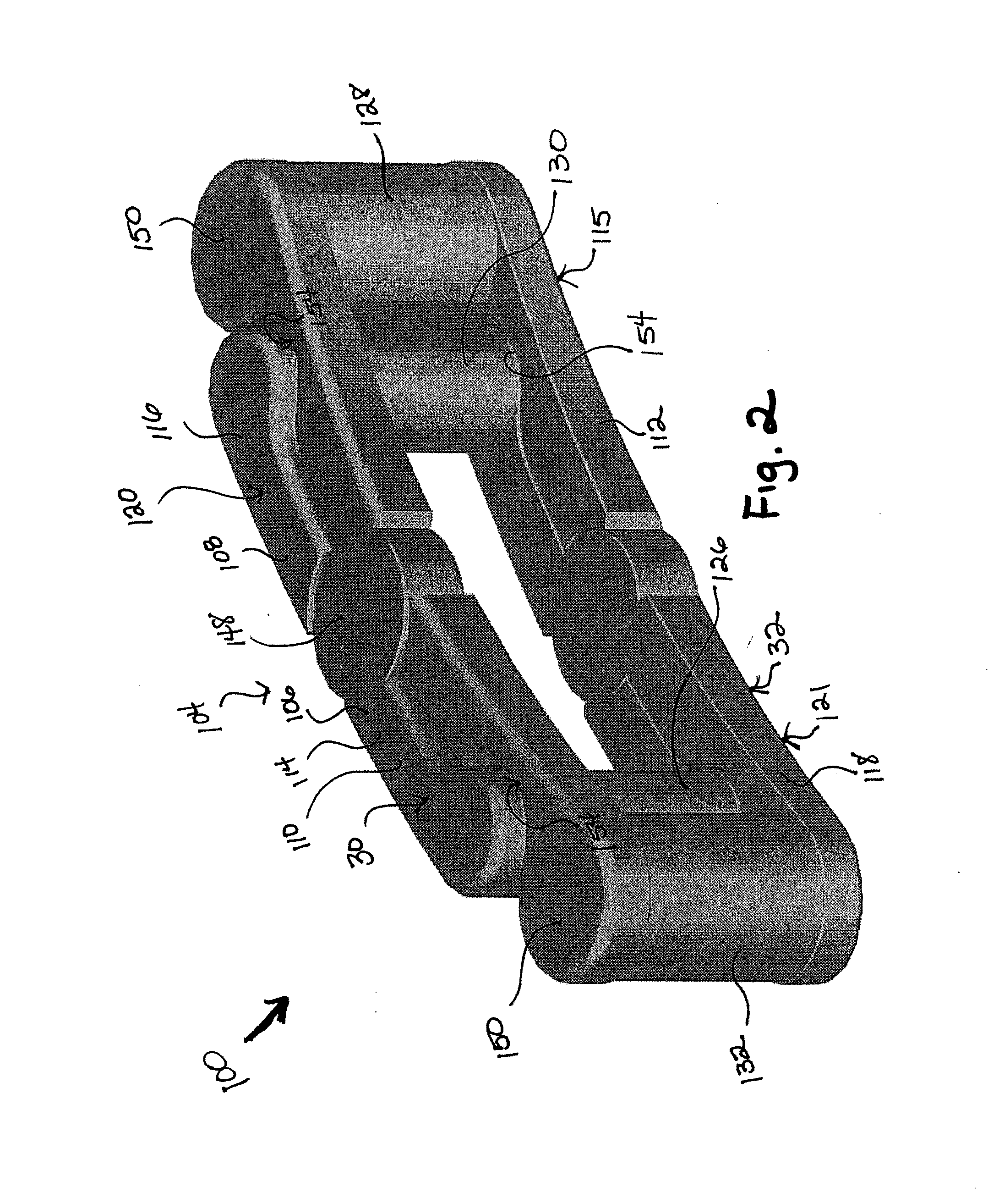
[0051]Referring now to the drawings wherein the showings are for purposes of illustrating one or more embodiments of the invention only and not for purposes of limiting the same, FIG. 1 shows a portion of a spinal column, a spinal segment 10 that may use the implant 100 (shown in FIGS. 2-5) of this invention. The spinal segment 10 is made up of two vertebrae 12, 14 attached together by ligaments with a disc 16 separating them. Facet joints 18 fit between the two vertebrae 12, 14 and allow for movement. The neural foramen 20 between the vertebrae 12, 14 allow space for the nerve roots to travel freely from the spinal cord 28 to the body. The disc 16 occupies the intradiscal space 22. By intradiscal space 22 it is meant the space usually occupied by the disc 16 between two adjacent vertebral bodies 12, 14 and more specifically the space 22 between adjacent endplates 24, 26 of the vertebral bodies 12, 14 as shown. As the components and operation of a spinal column is well known to thos...


PUM


Abstract

An implant has a first contact surface to contact a first vertebral body endplate and a second contact surface to contact a second vertebral body endplate adjacent the first vertebral body. The implant is deployable, when positioned within an intradiscal space between the first and second vertebral bodies, from a first non-expanded condition where the first contact surface has a first effective footprint area A1 to a second expanded condition where the first contact surface has a second effective footprint area A2. The ratio A2/A1 is at least 1.05.

Description

I. BACKGROUND OF THE INVENTION[0001]A. Field of Invention[0002]This invention pertains to the art of methods and apparatuses regarding spine surgery and more specifically relates to surgical procedures, associated instrumentation and an implant to be positioned within an intradiscal space between two adjacent vertebral bodies.[0003]B. Description of the Related Art[0004]The volume of spinal surgeries to treat degenerative disc and facet disease has steadily increased over the past decade, fueled by population demographics and advancements in diagnostic and instrumentation adjuncts. Improvements in intraoperative radiological imaging and surgical technique have generated a great deal of interest in applying minimally invasive surgical (MIS) techniques to spinal applications. As in other surgical subspecialties, it is hoped such minimally invasive techniques applied to spinal surgery will result in less soft tissue trauma, less operative blood loss, reduced operative time, faster reco...

Claims


Application Information

Patent Timeline
IPC IPC(8): A61F2/44
CPCA61F2/442A61F2/30744A61F2/30965A61F2/4425A61F2/4455A61F2/4601A61F2/4611A61F2/4684A61F2002/2835A61F2002/30014A61F2002/30179A61F2002/30462A61F2002/30471A61F2002/30492A61F2002/30505A61F2002/30561A61F2002/30563A61F2002/30568A61F2002/30579A61F2002/30616A61F2002/30836A61F2002/30841A61F2002/30904A61F2002/4415A61F2002/4619A61F2220/0075A61F2220/0091A61F2310/00011A61F2310/00017A61F2310/00023A61F2310/00179
Inventor FABIAN, HENRY F.CICORETTI, LARRY A.
Owner FABIAN HENRY F
Why Eureka
Try Eureka