Laser irradiation apparatus and bright point correction method for liquid crystal display panel using the same

Active Publication Date: 2014-01-09
V TECH CO LTD
View PDF8 Cites 12 Cited by
  • Summary
  • Abstract
  • Description
  • Claims
  • Application Information

AI Technical Summary

Benefits of technology

[0024]According to a seventh aspect of the invention, it is possible to widen respective irradiation areas of the first laser light and the second laser light radiated to a liquid crystal display panel. Accordingly, it is possible to improve the efficiency of a peeling

Problems solved by technology

However, since such a conventional laser irradiation apparatus has two laser generators for generating two laser lights having different wavelengths, and is configured to switch ON and OFF states of these generators to extract a laser light having a specific wavelength, it is difficult to downsize the apparatus.
However, in this method, since the plurality of optical paths is provided so as to spread in the lateral direction, it is not easy to downsize the apparatus.
Further, it is also possible to extract a laser light having a specific wavelength by using a filter from mixed laser lights having different wavel

Method used


Image

  • Laser irradiation apparatus and bright point correction method for liquid crystal display panel using the same
  • Laser irradiation apparatus and bright point correction method for liquid crystal display panel using the same
  • Laser irradiation apparatus and bright point correction method for liquid crystal display panel using the same

Examples


Example

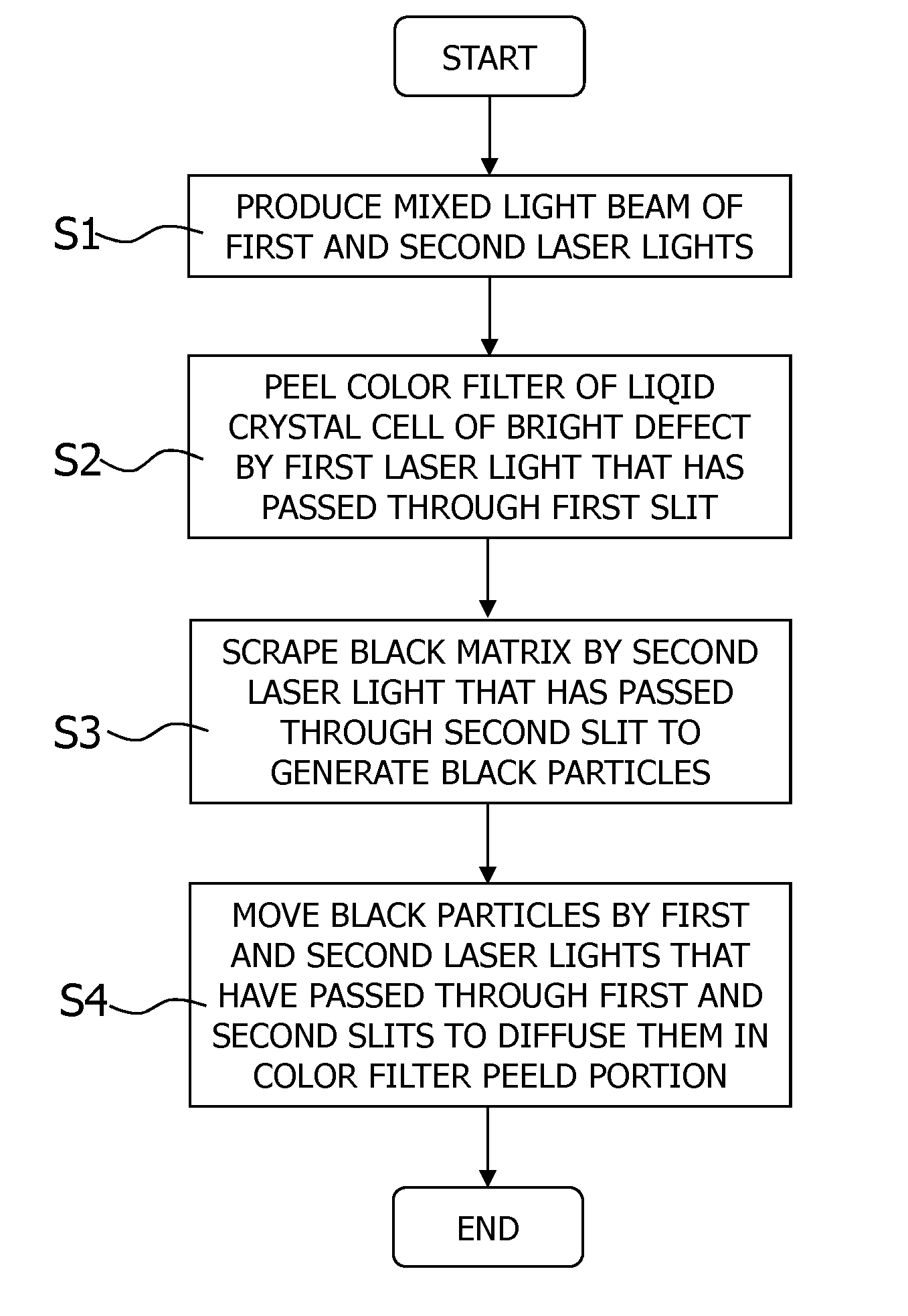
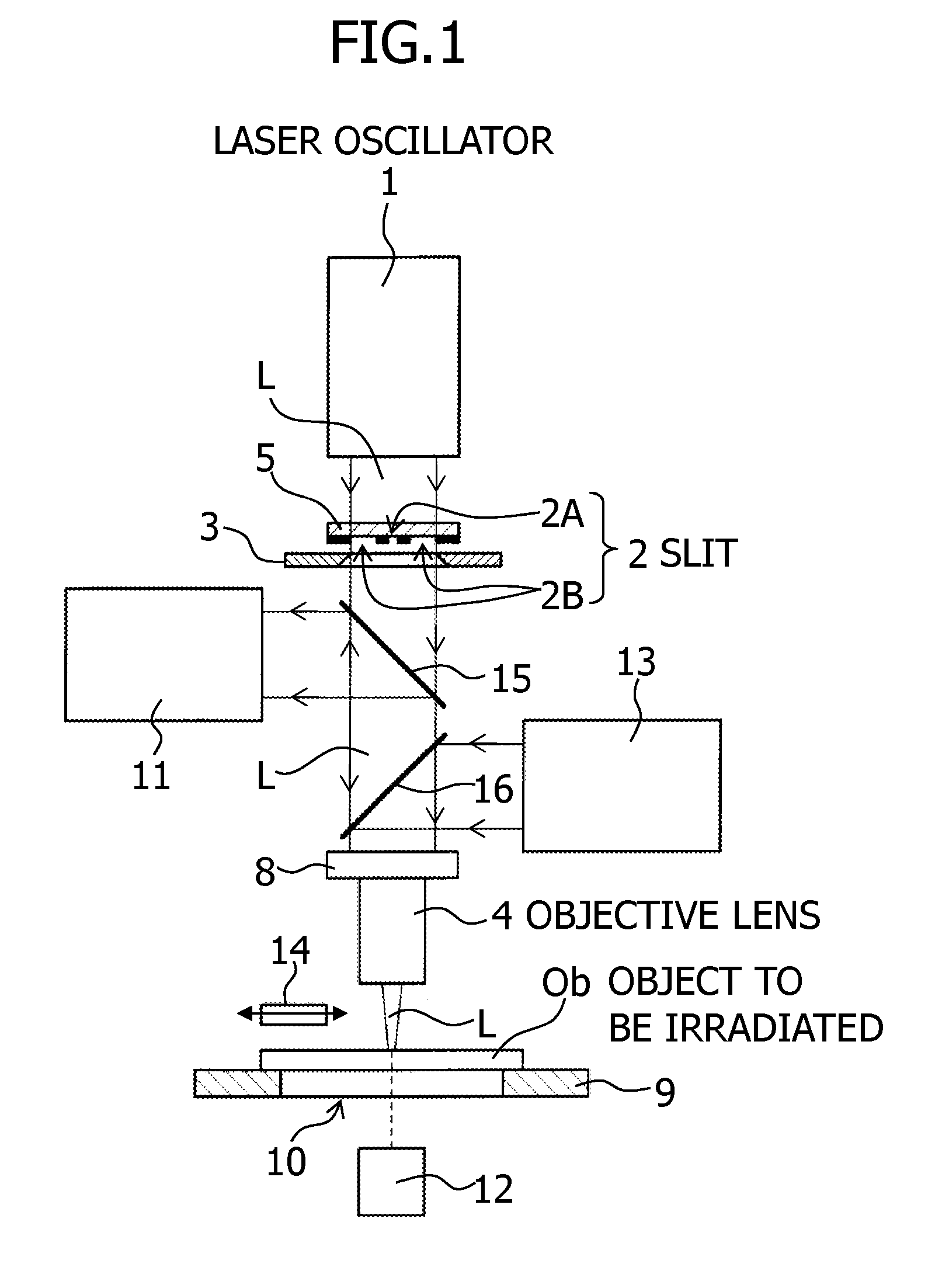
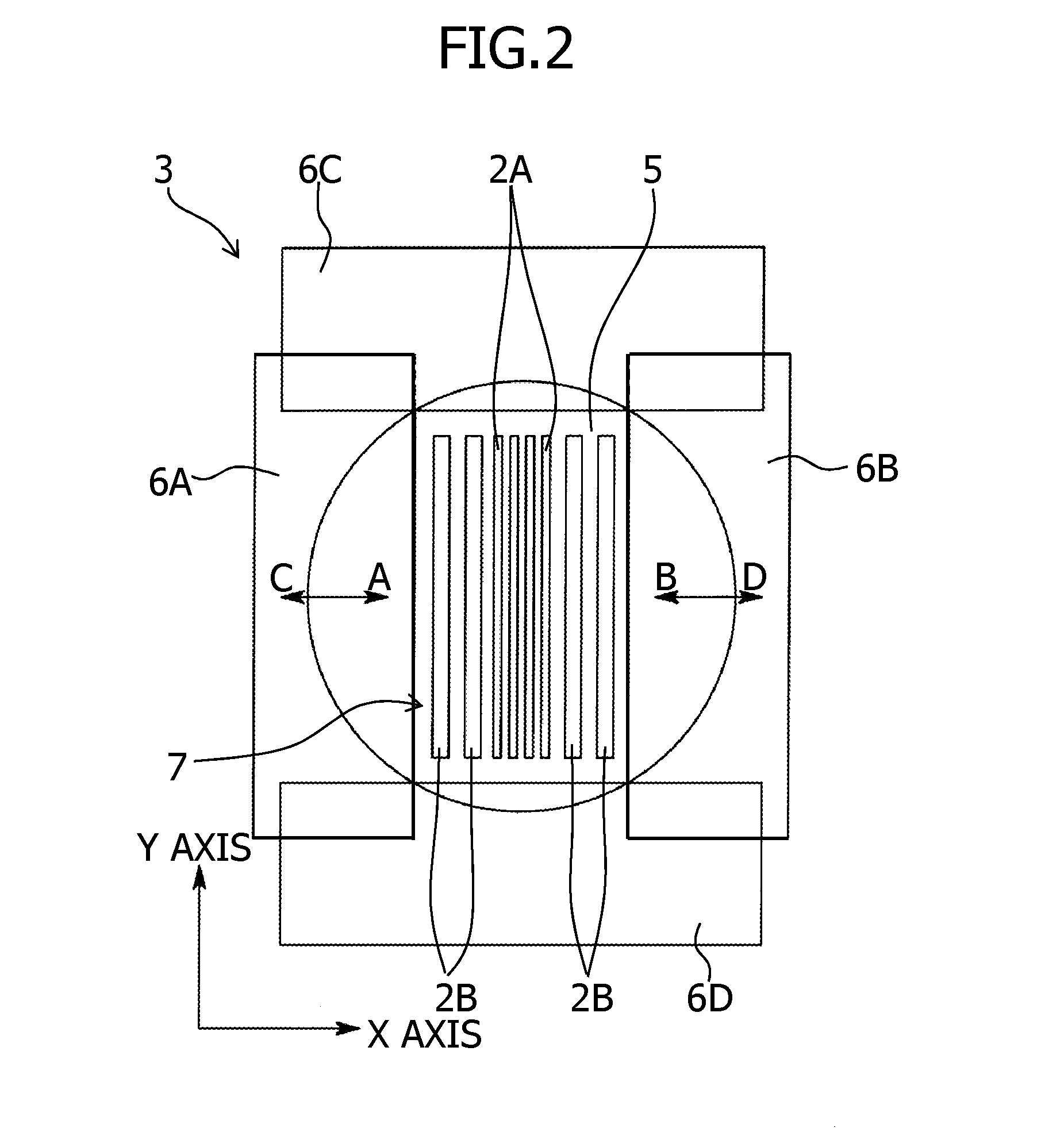
[0032]Hereunder, embodiments of the present invention will be described in detail with reference to the attached drawings. FIG. 1 is a front view illustrating an embodiment of a laser irradiation apparatus according to the embodiment of the present invention. This laser irradiation apparatus is configured to select among a plurality of laser lights having different wavelengths a laser light having a wavelength according to the purpose of irradiation and to irradiate an object to be irradiated with the selected laser light, and the apparatus includes a laser oscillator 1, a slit 2, a light-blocking device 3 and an objective lens 4.

[0033]The above laser oscillator 1 produces a plurality of laser lights having different wavelengths, which is, for example, a solid-state YAG laser or an excimer laser and configured to produce from a fundamental wave of 1064 nm a first laser light that is a fourth harmonic wave of 266 nm and a second laser light that is a third harmonic wave of 355 nm, an...


PUM

PropertyMeasurementUnit
Widthaaaaaaaaaa
Wavelengthaaaaaaaaaa
Optical propertiesaaaaaaaaaa

Abstract

The present invention is a laser irradiation apparatus which is capable of selecting among a plurality of laser lights L having different wavelengths a laser light of a wavelength according to a purpose of irradiation and irradiating an object Ob to be irradiated with the laser light having the wavelength. The laser irradiation apparatus includes: on an optical path of a mixed light beam of the plurality of laser lights L having different wavelengths, a slit having a width corresponding to a diffraction limit of the laser light having the shortest wavelength among the plurality of laser lights L having different wavelengths; and an objective lens for focusing a laser light that has passed through the slit, on the object Ob to be irradiated.

Description

[0001]This application is a continuation application of PCT / JP2012 / 054973, filed on Feb. 28, 2012.BACKGROUND OF THE INVENTION[0002]1. Field of the Invention[0003]The present invention relates to a laser irradiation apparatus which is capable of selecting among a plurality of laser lights having different wavelengths a laser light having a wavelength according to the purpose of the irradiation and irradiating an object to be irradiated with the laser light having the wavelength, in particular, relates to a downsized laser irradiation apparatus capable of extracting from a mixed laser light of a plurality of laser lights having different wavelengths a laser light having the shortest wavelength with high wavelength purity, and a bright point correction method for a liquid crystal display panel using such an apparatus.[0004]2. Description of Related Art[0005]Conventionally, this sort of laser irradiation apparatus is provided with a first laser generator which generates a first laser li...

Claims


Application Information

Patent Timeline
IPC IPC(8): G02F1/133G02F1/13B23K26/00B23K26/066G02B5/20G02F1/1335
CPCG02F1/13306B23K26/0613B23K26/066G02F1/1309G02F1/133509B23K26/064B23K26/359B23K26/55G02F1/13
Inventor OTAKI, KAZUYA
Owner V TECH CO LTD
Why Eureka
Try Eureka