Luminescent keyswitch module and keyboard thereof

a technology of luminescent keyswitch and module, which is applied in the field of keyswitch and a keyboard, can solve the problems of reducing the luminous effect of the keycap and negatively affecting the visual experience of the user, and achieves the effect of improving the backlighting quality of increasing the divergence angle of light emitted, and improving the luminescent keyswitch modul

Active Publication Date: 2014-03-06
CHICONY ELECTRONICS
View PDF4 Cites 5 Cited by
  • Summary
  • Abstract
  • Description
  • Claims
  • Application Information

AI Technical Summary

Benefits of technology

[0008]In order to solve the problems of the prior art, the disclosure provides an improved luminescent keyswitch module. The luminescent keyswitch module entails the use backlighting, rather than directly emitting light toward a keycap of a keyswitch, so that the luminous effect obtained by the luminescent keyswitch module is more even. The luminescent keyswitch module of the disclosure further includes a diffusion structure disposed next to a light source, so as to increase the divergence angle of the light emitted by the light source, thereby effectively improving the backlighting quality of the luminescent keyswitch module. Moreover, the reflector of the disclosure is directly mounted to a base plate, but the reflector is not adhered to a light guide plate. Therefore, when the emitted light is reflected to the light guide plate by the reflector, the light is not obscured and the luminous quality is not affected.

Problems solved by technology

However, because the conventional illuminated keyboard is configured such that light-emitting diodes are directly disposed on a membrane circuit board and emit light toward keycaps of the keyswitches, uneven light is a problem that easily occurs, thereby greatly reducing the luminous effect of the keycaps.
Moreover, the foregoing approach is such that the luminous region of each of the keyswitches is limited within a small area, negatively affecting the visual experience of a user.

Method used


Image

  • Luminescent keyswitch module and keyboard thereof
  • Luminescent keyswitch module and keyboard thereof
  • Luminescent keyswitch module and keyboard thereof

Examples


Embodiment Construction

[0031]Reference will now be made in detail to the present embodiments of the disclosure, examples of which are illustrated in the accompanying drawings. Wherever possible, the same reference numbers are used in the drawings and the description to refer to the same or like parts.

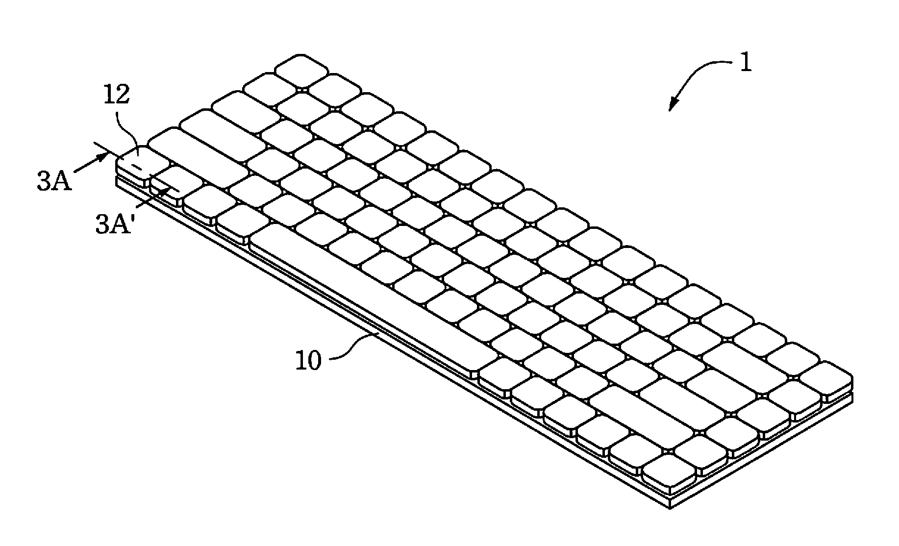
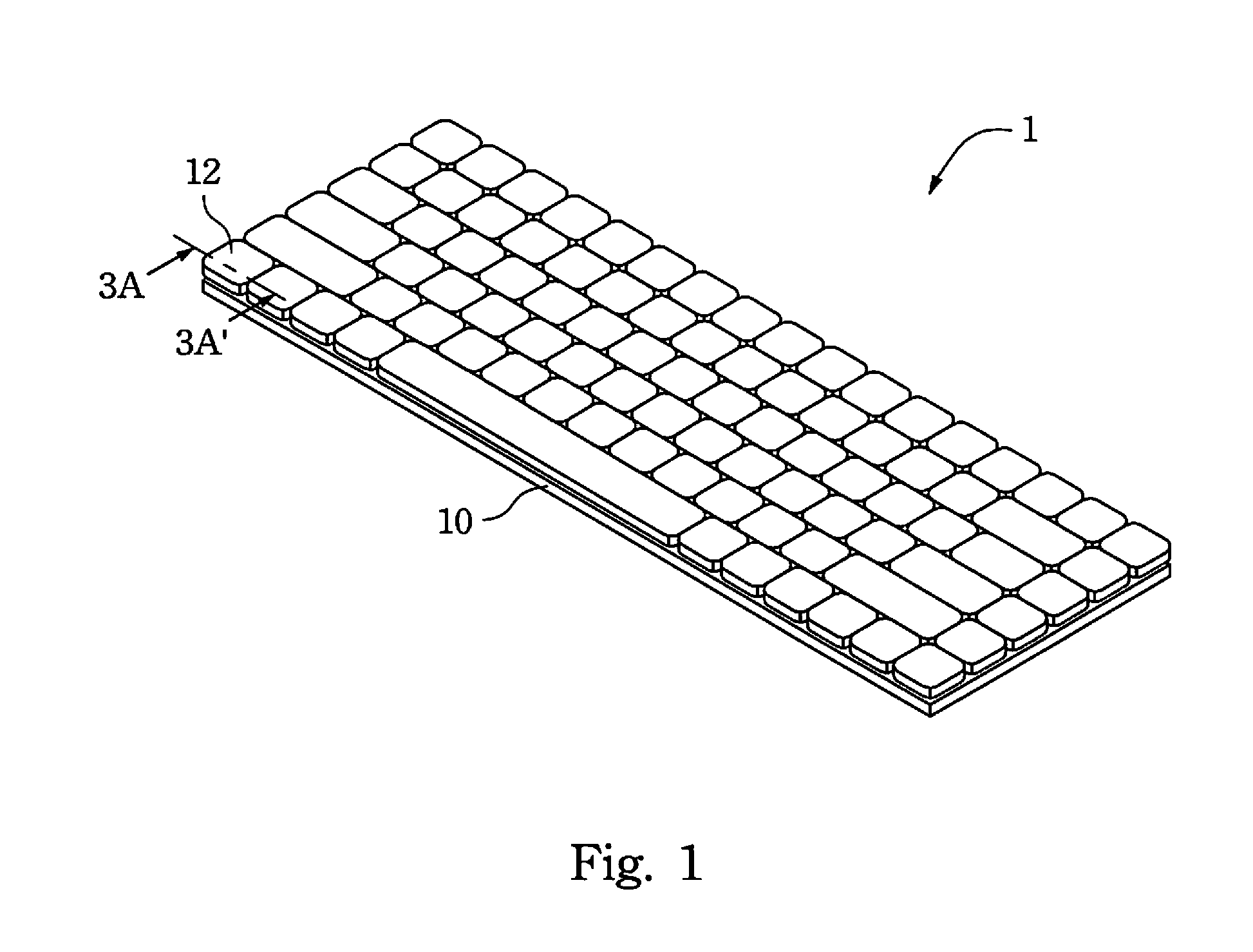
[0032]FIG. 1 is a perspective view of a keyboard 1 according to an embodiment of the disclosure.

[0033]As shown in FIG. 1, the keyboard 1 of the disclosure can be an external keyboard (e.g., a keyboard with a PS / 2 interface or a keyboard with a USB interface) used in a desktop computer, or can be a part of a computer system having an input device that is in the form of a keyboard (e.g., a notebook computer or a laptop computer), but the disclosure is not limited in this regard. That is, the concepts of the keyboard 1 of the disclosure can be used in any electronic product that adopts luminescent keyswitch modules to be the input interface.

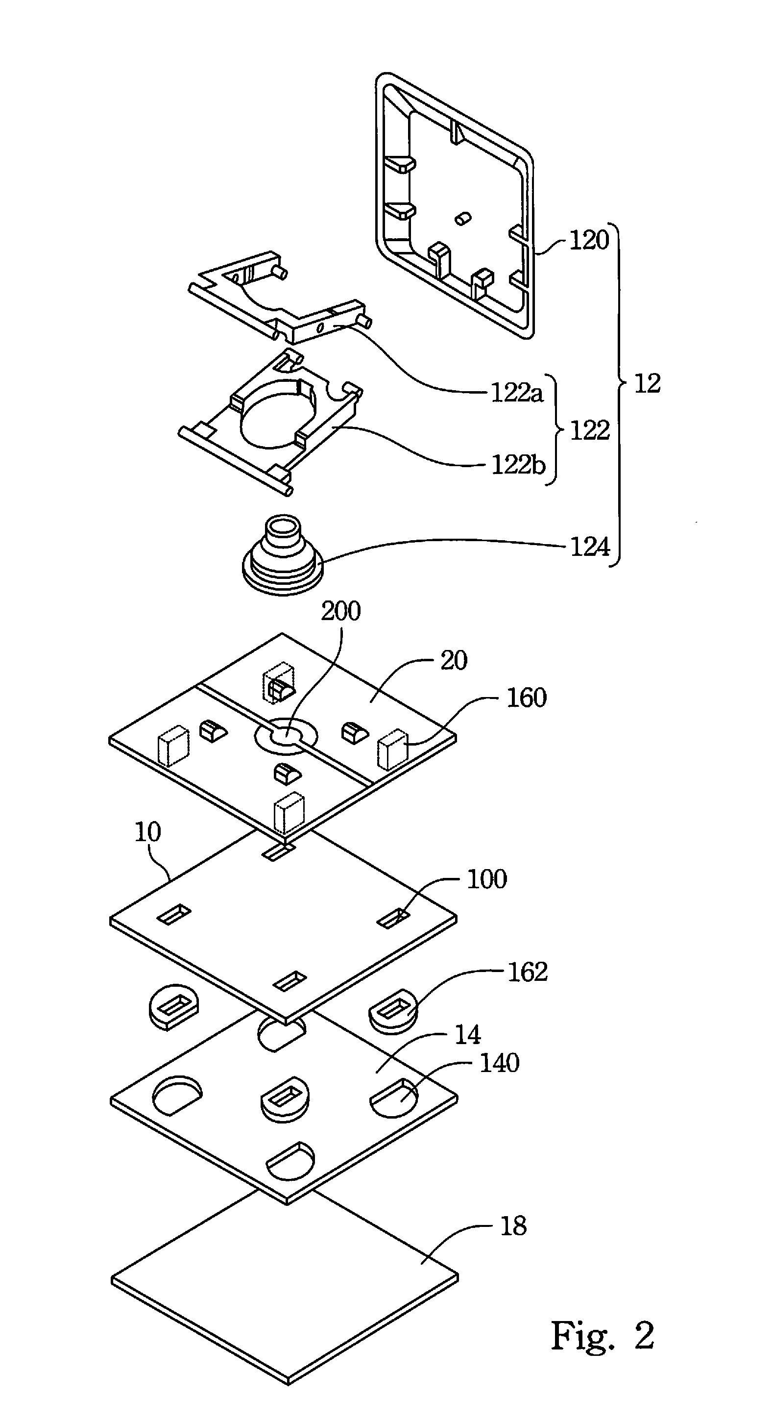
[0034]FIG. 2 is an exploded perspective view of a luminescent keyswitch ...


PUM


Abstract

A luminescent keyswitch module includes a base plate, a keyswitch, a light guide plate, a light source, a diffusion structure, and a reflector. The keyswitch is disposed on the base plate. The light guide plate, disposed under the base plate, has an accommodating space communicated with a through hole of the base plate. The light source passes through the through hole, is accommodated in the accommodating space, and emits light having a first divergence angle. The diffusion structure is accommodated in the accommodating space and located between the light source and the light guide plate. The light passes through the diffusion structure. The light leaving the second light exit surface has a second divergence angle larger than the first divergence angle. The reflector is disposed under the light guide plate, so as to reflect the light to pass through the light guide plate and the base plate to the keyswitch.

Description

RELATED APPLICATIONS[0001]This application claims priority to Taiwan Application Serial Number 101216820, filed Aug. 31, 2012, which is herein incorporated by reference.BACKGROUND[0002]1. Technical Field[0003]The present disclosure relates to a keyswitch and a keyboard including the keyswitch.[0004]2. Description of Related Art[0005]A keyboard is an essential input device for inputting characters or numbers when using a personal computer. Consumer electronics used in daily life or large-scale processing equipment used in industry need input devices having keyswitch structures for operating the consumer electronics products and the processing equipment.[0006]In order to allow visibility when working in dark places, keyboards having LED (light-emitting diode) backlights have been developed, further increasing the great diversity of keyboards. A known configuration involves disposing each of the keyswitches of the keyboard (or each of the keyswitches thereof requiring visibility) on a ...

Claims


Application Information

Patent Timeline
Patent Type & Authority Applications(United States)
IPC IPC(8): H01H13/83H01H13/10
CPCH01H13/83H01H13/10H01H2219/056H01H3/125H01H2219/062H01H2219/014H01H2219/06
Inventor CHEN, CHIEN-SHUO
Owner CHICONY ELECTRONICS
Why Eureka
Try Eureka