Method and apparatus for micro-treating iron-based alloy, and the material resulting therefrom

a technology of iron-based alloys and micro-treatment, which is applied in the field of treated iron-based alloys, can solve the problems of large equipment pieces for steel processing, high cost and dangerous heated fluids, and inability to produce desirable products, etc., and achieves the effects of reducing the need, reducing the quantity of bainite and/or martensite, and quick and inexpensive treatmen

Inactive Publication Date: 2015-01-08
SFP WORKS
View PDF5 Cites 2 Cited by
  • Summary
  • Abstract
  • Description
  • Claims
  • Application Information

AI Technical Summary

Benefits of technology

[0013]An advantage of the invention is that a low carbon iron-based alloy, potentially with varying desired thicknesses may be treated quickly and inexpensively to yield a high quantity of bainite and / or martensite that will be ready to be utilized without further formations or treatments.
[0014]Another advantage of the invention is that it uses a highly concentrated heating unit using a highly combustible gas, such as a propane or oxygen heating, so that high temperature flames may be blasted against an iron-based alloy surface to about 2500° F. in a relatively short period of time. The heating unit alleviates the need for increased fuel costs to fire up a big furnace, as the heating is so localized.
[0015]A further advantage of the invention is that it uses a hard quench, so that quench cracking and workpiece distortion is alleviated.

Problems solved by technology

Previous attempts have met with limited success in that they did not always produce a desirable product.
Processing of steel generally takes large pieces of equipment, expensive and dangerous heated fluids, such as quenching oils and quenching salts, and tempering processes which include the use of ovens and residual heat from pouring molten steel followed by quenching in order to raise the hardness of the steel to a desirable value.
Since chemical processes accelerate at higher temperature, martensite is easily destroyed by the application of heat.
Since quenching can be difficult to control, most steels are quenched to produce an overabundance of martensite, and then tempered to gradually reduce its concentration until the right structure for the intended application is achieved.
Too much martensite leaves steel brittle, too little leaves it soft.

Method used


Image

  • Method and apparatus for micro-treating iron-based alloy, and the material resulting therefrom
  • Method and apparatus for micro-treating iron-based alloy, and the material resulting therefrom
  • Method and apparatus for micro-treating iron-based alloy, and the material resulting therefrom

Examples


example 1

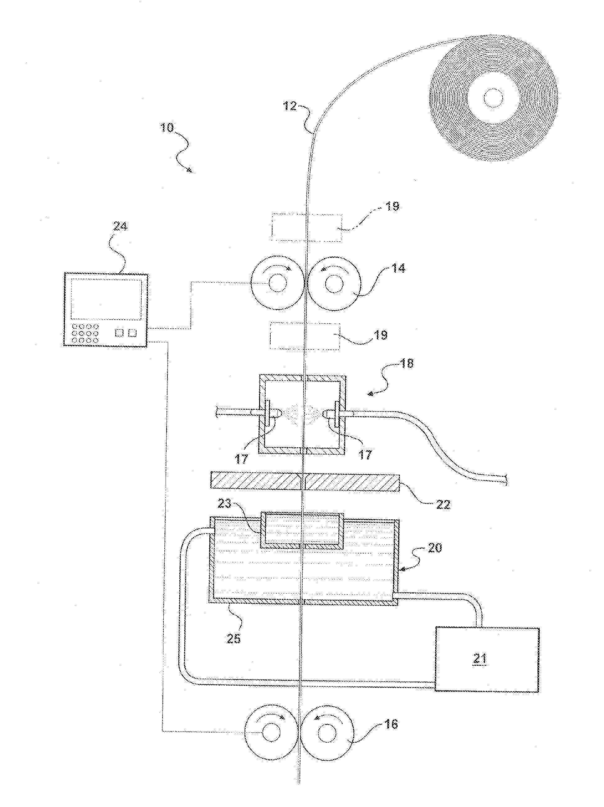
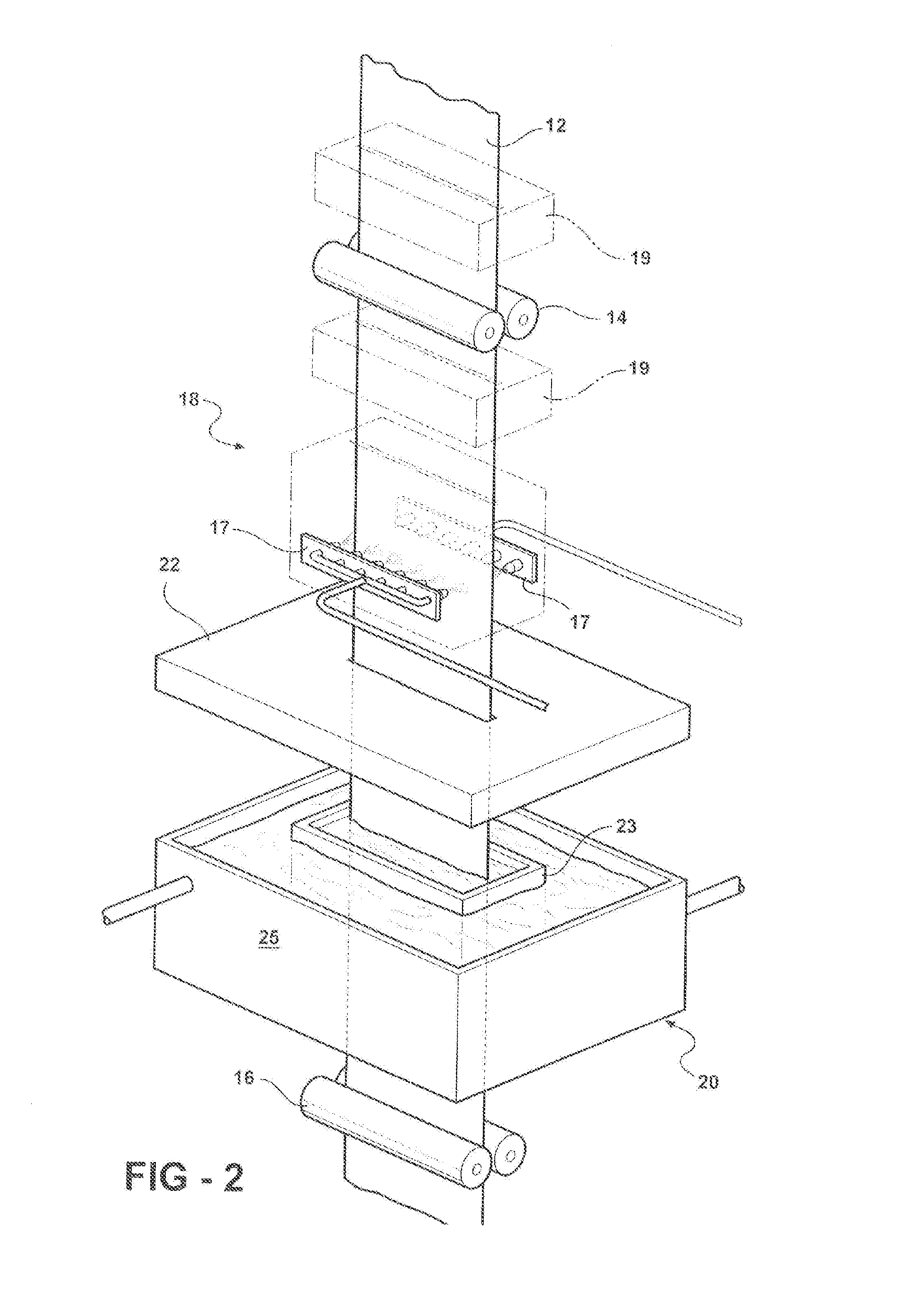
[0038]A strip of 1018-1020 low carbon steel of 0.064 inch thick by 3.02 inches wide was stretched under tension between two securement points in first and second tensioning units with a feed rate of 10.75 IPM (inches per minute) and a draw rate of 13.25 IPM. Between the securement points a primary heating unit blasted two sets of pinpoint high temperature flames, each about ½ inch in diameter towards the opposing faces of the steel strip to heat the steel to 1,900° F. As the steel moved and stretched downward through the first tensioning unit, a quenching unit bucket directed a cold water stream onto the heated steel strip under tension about ½ inch lower than the flame to cool the steel strip to about 57° F., yielding a steel that tested to be 30 Rc.

example 2

[0039]A strip of 8620 low carbon steel of 0.062 inch thick by about 3.00 inches wide was stretched between two securement points in a first and a second tensioning unit with a feed rate of about 10.75 IPM and a draw rate of about 13.25 IPM. Between the securement points a heating unit blasted two opposing sets of multiple pinpoint high temperature flames about ⅛ inch tall by 3 inches wide towards the opposing faces of the steel strip to heat the steel to about 2,350° F. As the steel moved and stretched downward through the first tensioning unit, a quenching unit directed a cold water stream onto the heated steel strip under tension about ¾ inch lower than the flames to cool the steel strip to about 70° F. within seconds, yielding a steel that tested to be 48 Rc. This material is found to have a micro-structural content that is 85 percent (85%) of bainite. The resulting thickness is controllably reduced from 0.062 inch to a range of 0.049 inch to 0.054 inch.

example 3

[0040]A strip of 1008 low carbon steel (about 0.036 percent carbon by weight) of 0.065 inch thick by 3.02 inches wide was stretched between two securement points in a first and a second tensioning units with a feed rate of about 10.75 IPM and a draw rate of from about 10.75 IPM to about 16 IPM. Between the securement points, a heating unit blasted two opposing sets of multiple pinpoint high temperature flames about ⅛ inch tall by about 3 inches wide towards the opposing faces of the steel strip to heat the steel to 2,250° F. As the steel moved and stretched downwards through the first tensioning unit, a quenching unit directed a cold water stream onto the heated steel strip under tension about ½ inch to 1 inch lower than the flame to cool the steel strip to about 70° F. within seconds, yielding a steel that tested to be from 1 to 36 Rc. This material is found to have a microstructure content that is mostly martensite. The resulting thickness is controllably reduced from 0.065 inch t...


PUM

PropertyMeasurementUnit
temperatureaaaaaaaaaa
Rockwell hardnessesaaaaaaaaaa
temperatureaaaaaaaaaa

Abstract

The invention discloses a process and apparatus for micro-treating an iron-based alloy including heating and immediately quenching to room temperature to produce high tensile iron-based alloy with varying thicknesses. The process may or may not be practiced with or without tension, under various controllable tensions in order to create desirable effects. The micro-treated iron-based alloy contains desirable bainite to increase its formability and tensile strength. The varying thickness of the iron-based alloys is desirable for different applications, such as forming automobile panels.

Description

CROSS REFERENCES TO RELATED APPLICATIONS[0001]This application is a divisional application from co-pending U.S. Parent application Ser. No. 11 / 718,969 and claims the benefit of U.S. Provisional Application No. 60 / 628,316 filed on Nov. 16, 2004, PCT International Application No. PCT / US2005 / 41444 and U.S. National Stage application Ser. No. 11 / 718,969 which is incorporated herein by reference.TECHNICAL FIELD[0002]This invention relates to treated iron-based alloys, and more particularly relates to a process and an apparatus for making the same and the material resulting therefrom which transforms low carbon steel and other iron-based alloys to bainite and / or martensite by micro-tempering or micro-treating the low carbon alloy.BACKGROUND OF THE INVENTION[0003]It has long been a goal of metallurgists to take low grade metals, such as low carbon steel, and turn them into high quality steels and more desirable products through inexpensive treatments, including annealing, quenching, and te...

Claims


Application Information

Patent Timeline
Patent Type & Authority Applications(United States)
IPC IPC(8): C21D9/48C21D1/18B62D29/00C21D1/34
CPCC21D9/48B62D29/007C21D1/18C21D1/34C21D1/20C21D1/56C21D1/673C21D2211/002C21D2211/008C21D2221/00B62D25/02
Inventor COLA, JR., GARY M.ZIOLKOWSKI, JEFF W.ZIOLKOWSKI, TODD C.
Owner SFP WORKS
Why Eureka
Try Eureka