This helps you quickly interpret patents by identifying the three key elements:
Problems solved by technology
Method used
Benefits of technology
[0012]An aspect of the present invention provides a medical insertion apparatus that may dete
Problems solved by technology
After the decompression surgery, spinal segments may be unstable.
When the unstabl
Method used
Image
Click on the blue label to locate the original text in one second.
Reading with bidirectional positioning of images and text.
Examples
Embodiment Construction
[0067]Reference will now be made in detail to exemplary embodiments of the present invention, examples of which are illustrated in the accompanying drawings, wherein like reference numerals refer to the like elements throughout. Exemplary embodiments are described below to explain the present invention by referring to the figures.
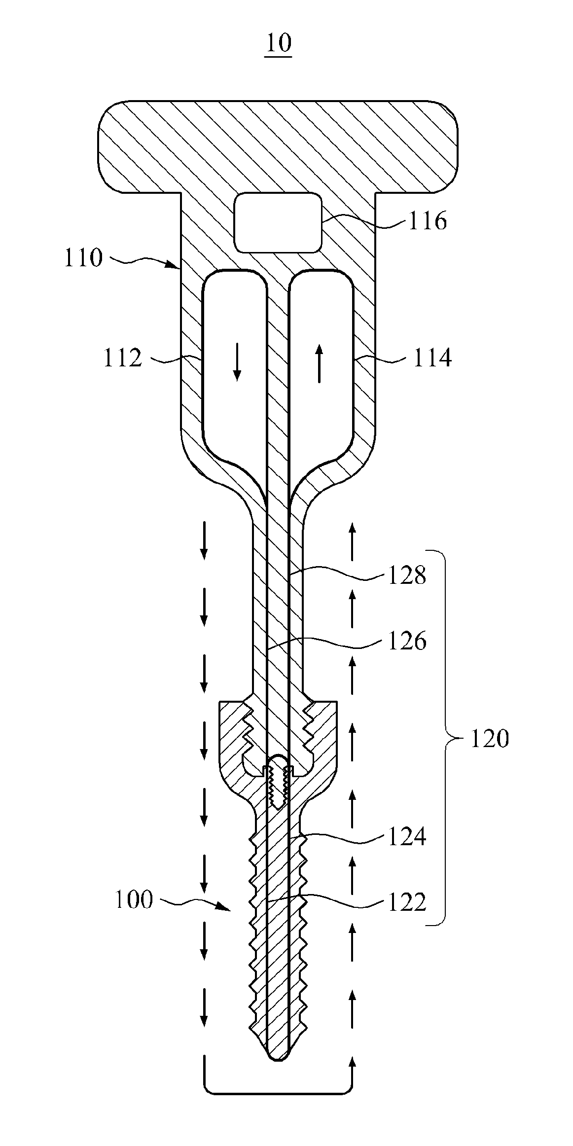
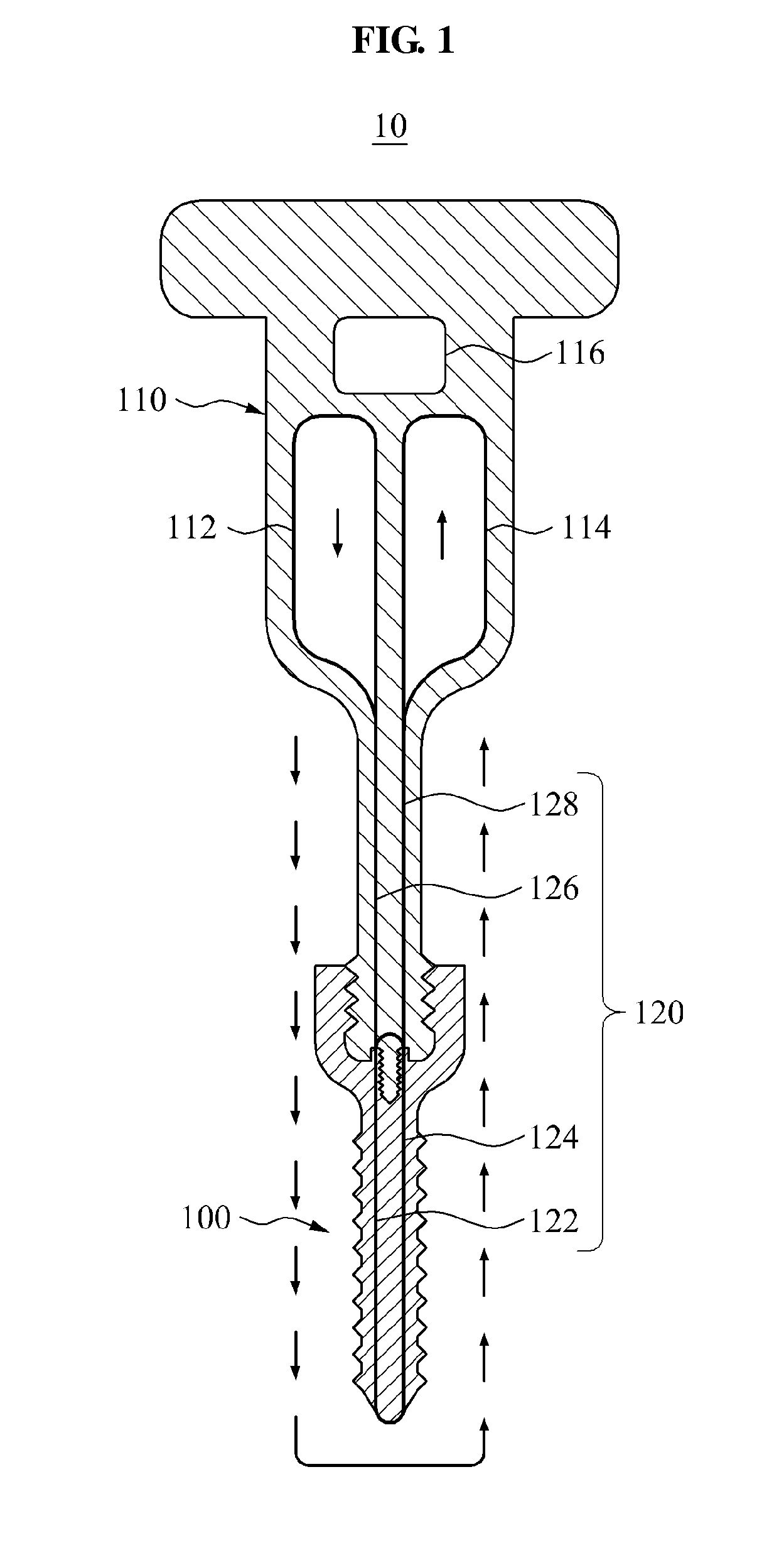
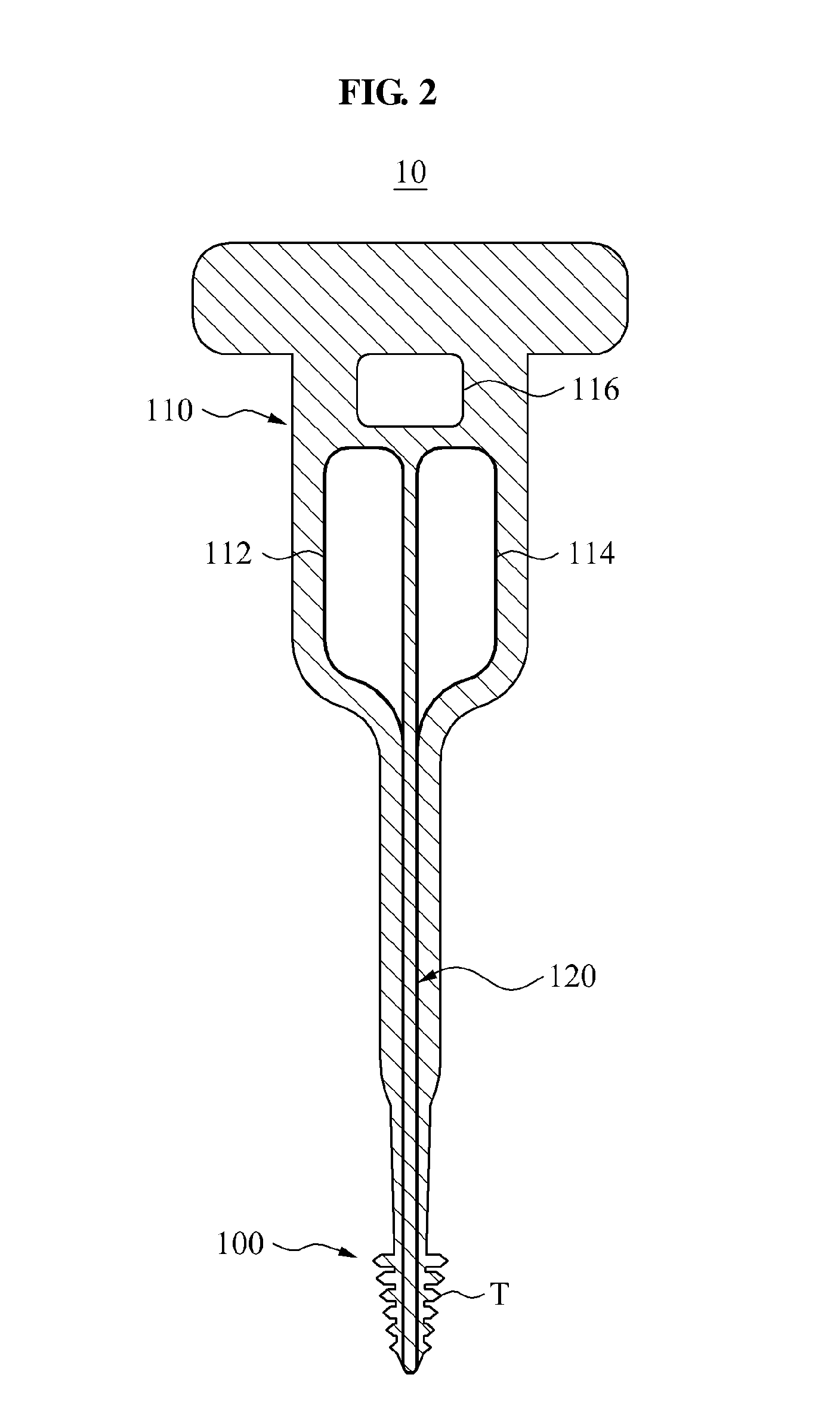
[0068]FIG. 1 is a view illustrating a medical insertion apparatus 10 according to an embodiment of the present invention. FIG. 2 is a view illustrating a screw body 100 provided in a form of a tapping screw in the medical insertion apparatus 10 according to an embodiment of the present invention. FIGS. 3A and 3B are views illustrating shapes of an externally exposed portion of the screw body 100 in the medical insertion apparatus 10 according to an embodiment of the present invention. FIG. 4 is a view illustrating the medical insertion apparatus 10 connected to an external terminal 130 according to an embodiment of the present invention.
[0069]Referring to F...
PUM
Abstract
Provided are a medical insertion apparatus including a screw body to be inserted into a body, and a conductive portion provided in the screw body and including an externally exposed portion, wherein the conductive portion may extend in a longitudinal direction of the screw body and form a single closed loop, and a medical insertion apparatus including a screw body to be inserted into a body, a driver to engage with the screw body to be used to fasten or loosen the screw body, and a conductive portion provided in the screw body and the driver and including an externally exposed portion on one side of the screw body, wherein a portion of the conductive portion disposed in the screw body and another portion of the conductive portion disposed in the driver may be electrically connected to each other.
Description
CROSS-REFERENCE TO RELATED APPLICATION[0001]This application claims the benefit of Korean Patent Application Nos. 10-2013-0101078, filed on Aug. 26, 2013, 10-2014-0028345, filed on Mar. 11, 2014, 10-2014-0028921, filed on Mar. 12, 2014, 10-2014-0034206 filed on Mar. 24, 2014, 10-2014-0034210, filed on Mar. 24, 2014, 10-2014-0034202, filed on Mar. 24, 2014, and 10-2014-0034203, filed on Mar. 24, 2014, in the Korean Intellectual Property Office, the disclosures of which are incorporated herein by reference.BACKGROUND[0002]1. Field of the Invention[0003]Embodiments of the present invention relate to a medical insertion apparatus, and more particularly, to a medical insertion apparatus that may be safely inserted into a body, increase a contact force between a conductor in a screw body and a conductor in a driver, and be efficiently connected to a nerve stimulating and monitoring apparatus.[0004]2. Description of the Related Art[0005]A medical insertion apparatus may be inserted into a ...
Claims
Application Information
Patent Timeline
Application Date:The date an application was filed.
Publication Date:The date a patent or application was officially published.
First Publication Date:The earliest publication date of a patent with the same application number.
Issue Date:Publication date of the patent grant document.
PCT Entry Date:The Entry date of PCT National Phase.
Estimated Expiry Date:The statutory expiry date of a patent right according to the Patent Law, and it is the longest term of protection that the patent right can achieve without the termination of the patent right due to other reasons(Term extension factor has been taken into account ).
Invalid Date:Actual expiry date is based on effective date or publication date of legal transaction data of invalid patent.