Needle for a syringe, syringe and corresponding control system

Pending Publication Date: 2019-10-24
LIGHTSENS MEDICAL SA
View PDF2 Cites 1 Cited by
  • Summary
  • Abstract
  • Description
  • Claims
  • Application Information

AI Technical Summary

Benefits of technology

The present invention is a needle-injection line-syringe system that includes a pressure sensor to detect pressure close to the needle tip and alert the operator when inappropriate pressure is detected, such as over-pressure caused by the needle being in a nerve. The alarm is controlled and activated electrically without delay. The pressure sensor also allows the needle to alert the operator when the injection speed is too high, preventing complications such as nerve injury or ischemic injury. The system does not require any modification of the system and is ergonomic and comfortable for the operator. The system also includes a memory card to record the injection pressure wave profile for analysis and proof of good clinical practice.

Problems solved by technology

However in many cases the definition provided by these imaging techniques is not sufficient to confirm beyond any doubt the exact position of the needle tip.
Even for an experienced operator, an injection carries the intrinsic risk of a needle tip wrong positioning, with consequent injection of a drug in the wrong tissue, organ, or cavity.
On the contrary, if the needle tip is located in a blood vessel, the fluid will flow easily, with a very limited resistance.
This is of course not accurate, as based only on a subjective feeling and the experience of the operator and not on objective and measured data.
While in some situation, the wrong site injection consequence will only be a diminished therapeutic effect, in other cases it can have serious consequences.
The intrinsic risk is of course to inadvertently puncture the nerve however nowadays cannot be completely excluded by any of the guidance techniques available.
The latter situation, called intraneural injection, is thought to be the main cause of the permanent severe nerve damage, which consequent loss of function, which represents the most feared complication of peripheral nerves blocks.
Also in case of central regional anesthesia procedures, such as spinal and epidural anesthesia, which can be performed under real time ultrasound guidance, but are nowadays still performed with anatomical landmarks, a significant cause of iatrogenic morbidity is due to inadvertent injection of the local anesthetic or the drug used (corticosteroids, ialuronic acid, contrast, etc.) in the wrong place (inside a root, either subdural instead of spinal, or vice versa when not completely out of target in the soft tissues).
Finally, another relatively common error, which can lead to dramatic consequences is the inadvertent intravascular injection of local anesthetics or drugs which are not meant for intravenous use.
This can cause acute neurotoxicity and cardiac arrest (in case of a local anesthetic) or thromboembolism (in case of certain corticosteroids).
In all these circumstances, a diverse injection pressure can be felt during the injection of the drug, but again this is just a subjective feeling which is not objectivable and measurable.
Although quite rare (about 4:10'000 cases) they are associated to a devastating impact on patients' quality of life, leading to loss of function, anesthesia, dysesthesia, paresthesia and chronic pain syndromes.
Moreover, not all the operators reacts in the same way to a supposedly excessive perceived injection pressure, being their judgments affected, among other factors, by their subjective interpretation, the lack of an objective measurement method, the injection method they use, the type of syringe and needle used, the speed of injection.
This device allows a certain degree of control on the injection pressure, however presents many problems which prevent it to be a definitive solution to the issues indicated above.
First it poses some ergonomic problems: many operators are disturbed by the presence of the tubes connecting the syringe and the needle to the device, as well as by the presence of the device itself, which alter the usual structure of the leaner system syringe-injection line-needle.
In order to check the pressure he or she is generating along the injection line at any time, the operator must constantly check the device, thus stopping to look the needle insertion point and the ultrasound machine monitor, with consequent risk of unintentional displacement of the needle tip during the injection procedure and following risks of both complications and block failure.
For this reasons, many anesthesiologists nowadays have not adopted the device in their daily clinical practice and they are unlikely to adopt it in the future.
Moreover, this device is also affected by many important limitations with regard to its accuracy, which definitely limit the actual clinical utility of the information provided about injection pressure.
Due to all this factors, the pressure detected by the sensor of the known device cannot be used to make precise assumption on whether the liquid is injected in the proper location or not.
In other words, this known device may give an information or feed-back to the operator on a possible wrong location being instead the location appropriate (false positive) or, on the opposite (and more dangerously), it may give a false information on a possible correct location for the injection when, instead, the location is wrong (false negative).
These accuracy issues translate into a lack of sensitivity and specificity in detecting intraneural injections, leading to a potentially significant failure in lowering the incidence of nerve injury.
Furthermore, the indicator gives the information with a certain delay and with low precision.
Finally the existing device does not provide any information about an injection pressure lower than expected, which can be associated to important complications of regional anesthesia, namely intravascular or unintentional spinal injection of local anesthetic.
It also does not give the possibility of record the injection pressures generated during the procedures and thus does not constitute a proof of good clinical practice in case of litigation.

Method used


Image

  • Needle for a syringe, syringe and corresponding control system
  • Needle for a syringe, syringe and corresponding control system
  • Needle for a syringe, syringe and corresponding control system

Examples


Embodiment Construction

[0098]With reference to the annexed drawings, it is hereafter disclosed and indicated with reference number 1 a needle according to the present invention, and more particularly a needle adapted to be plugged to a tube and / or to a syringe including a liquid, the liquid being directed to be injected in the body of a patient for a predetermined application. Just as example and without limiting the scope of protection of the invention, the application may be an anaesthesia and the liquid may be a local anaesthetic; in such application, it is important to avoid that the liquid is not injected in a nerve.

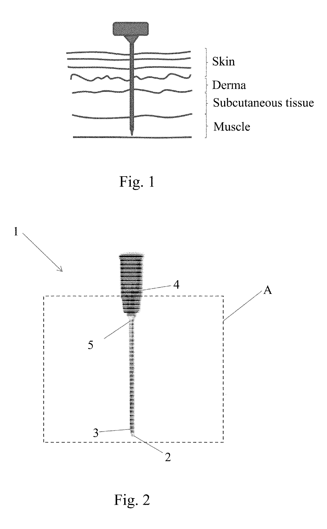
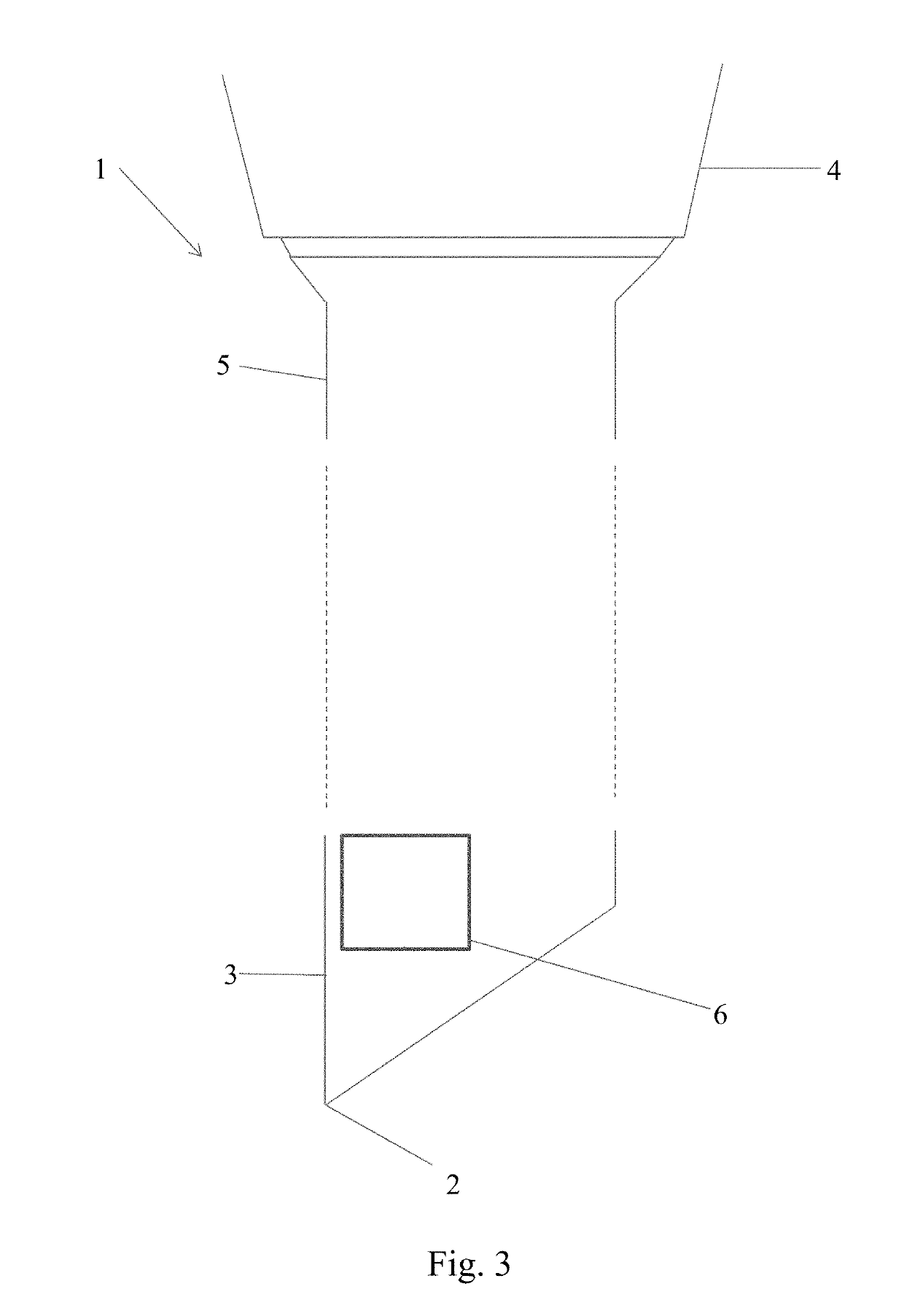
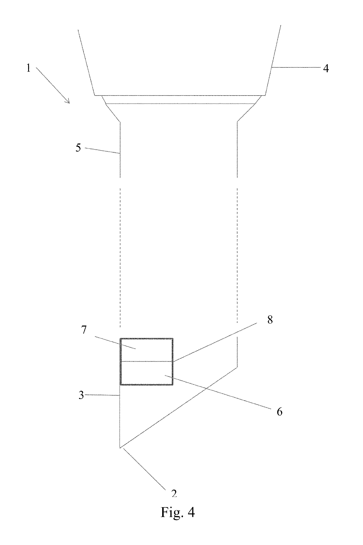
[0099]According to the present invention, the needle 1 has a tip 2 at one end 3, a hub 4 at the other end 5, as schematically represented in FIG. 2. FIG. 3, is an enlarged cross section of a portions A of FIG. 1, representing a sensor 6 inside the needle. The sensor is in the needle shaft. Preferably, the sensor is at the tip portion 2 of the needle.

[0100]During use, the needle passage th...


PUM


Abstract

It is disclosed a needle (1) for a syringe, including a tip (2) at one end (3) of the needle, adapted to penetrate a body tissue during usage of the syringe, and a hub (4) at the other end (5) of the needle, to attach the needle to the syringe. A pressure sensor (6) is in the needle; means (7) are provided to transmit outside the needle a pressure value sensed by the pressure sensor (6) in the needle.

Description

FIELD OF APPLICATION[0001]The present invention relates to a needle for a syringe.[0002]The present invention also relates to a syringe, and more particularly to a syringe and to a control system adapted to alert a user if a liquid is injected through the syringe in or near body tissues or body fluids not adapted to be addressed by the liquid.PRIOR ART[0003]In daily medical practice, injections of a liquid into a tissue, organ, or body cavity is extremely common, including steroids, local anaesthetics, hyaluronic acid, etc.[0004]In performing injections, it is important to identify the proper location at which injecting the fluid. In the vast majority of cases these injections are performed with a blind technique, i.e. according to external anatomic markers, or under ultrasound, fluoroscopic or CT guidance. However in many cases the definition provided by these imaging techniques is not sufficient to confirm beyond any doubt the exact position of the needle tip.[0005]Even for an exp...

Claims


Application Information

Patent Timeline
IPC IPC(8): A61M5/48
CPCA61M2205/583A61M2205/3317A61M2205/3507A61M5/488A61M2205/581A61M2205/18A61M5/486A61M2005/3125A61M2205/3344A61M2202/048A61M5/16854A61M5/178A61M2205/3355A61M2205/582
Inventor LEONARDI, MATTEOSAPORITO, ANDREAQUADRI, CHRISTIAN
Owner LIGHTSENS MEDICAL SA
Why Eureka
Try Eureka